Adjustment
2-02
24V = 4% ED
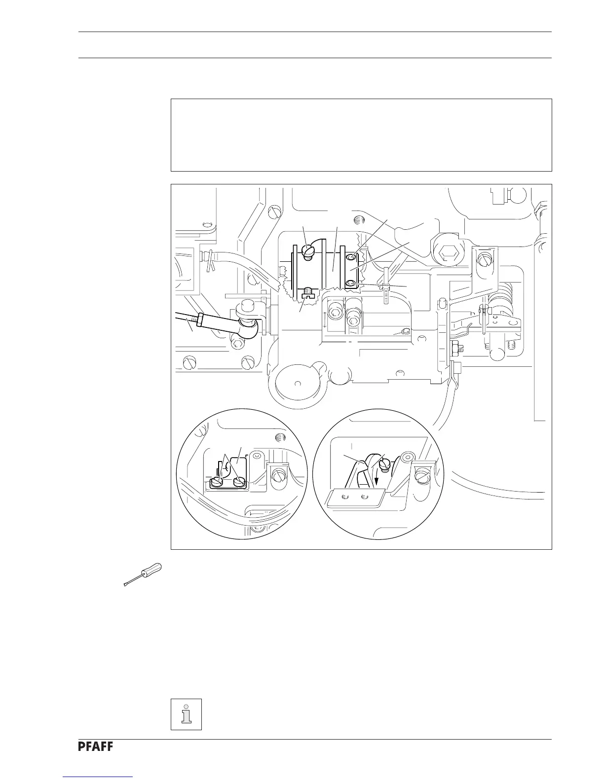
2.05 Pre-adjusting the control cam
Requirements
At the t.d.c of the needle bar,
1. the beginning of the highest point of the trip of the control cam 6 sould be positioned
under the tip of pawl 8 and
2. the right-hand side of the trip should be flush with the right-hand side of pawl 8.
● Pull the ball heads of connecting rod 1 off the ball pin at the cutting and control units
and remove connecting rod 1.
● Loosen screws 2 and retaining spring 3 together with the cover disk.
● Loosen screws 4 and 5.
● Twist or shift control cam 6 in accordance with requirement 1 or requirement 2 as
required.
● Tighten screws 4 firmly.
● Push fixing collar 7 onto control cam 6.
● Tighten screws 5 firmly.
Connecting rod 1 and retaining spring 3 stay dismantled for further
adjustments.
3
2
1
8
6
4 6
4
5
5
7
Fig. 2 - 01
2 - 2