Adjustment
2-11
24V = 4% ED
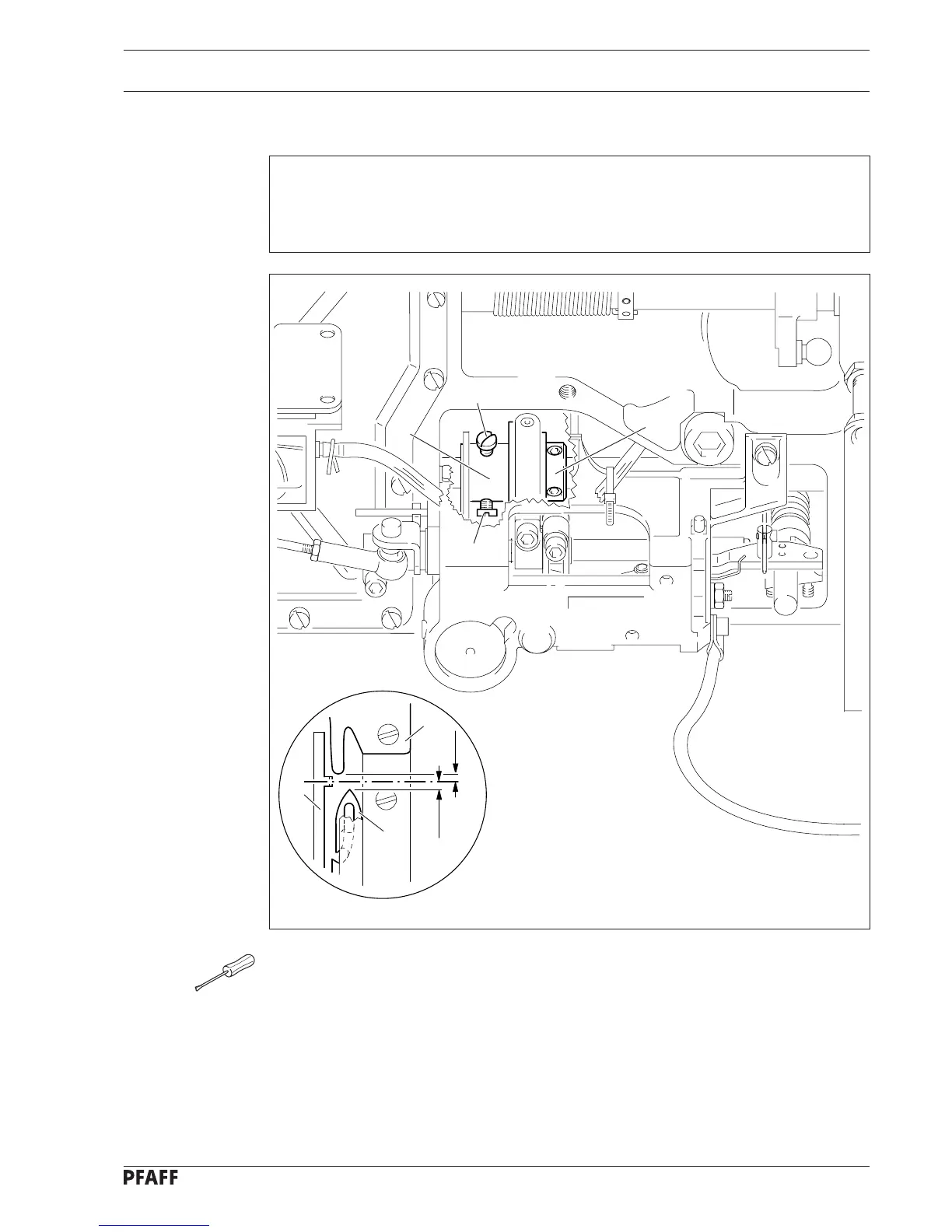
2.13 Re-adjusting the control cam
Requirement
When the end of the hook plate 1 is positioned 2 mm behind the middle of the lug of the
bobbin case position finger, the distance between the tip of the thread catcher 6 and the
middle of the lug should also be 2 mm.
● Position the needle bar at b.d.c
● Activate the engaging lever manually.
● Turn the hand wheel until the distance between the end of hook plate 1 and the middle
of the lug of the bobbin case position finger 2 is 2 mm.
● Turn control cam 3 (screws 4) in accordance with the requirement and bring it into
contact with fixing collar 5.
6
2
1
2 mm
2 mm
4
4
3
5
2 - 10
Fig. 2 - 09