Do you have a question about the Pfeiffer Vacuum ATH 2800 MT and is the answer not in the manual?
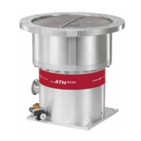
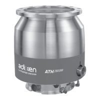
This document describes the Adixen ATH 2800 M/MT and ATH 3200 M/MT turbopumps, which are magnetically levitated turbopumps designed for various industrial and research applications.
The ATHM pump integrates the advantages of a multi-staged turbomolecular pump with a spiral helix molecular drag section. This design provides high pumping speeds and high ultimate vacuum, with the molecular drag section extending forevacuum tolerance and high compression ratio. The pump operates on a principle where the rotor is magnetically levitated, eliminating mechanical contact and ensuring a clean vacuum. The mobile assembly, comprising the turbo rotor and shaft, is driven by electromagnets housed in an active bearing. The mobile rotor has 5 axes of freedom monitored by 5 active magnetic bearings. An unbalance force rejection control system electronically monitors the rotor position, allowing it to rotate in its own axis of inertia. This system automatically compensates for any imbalance of the rotor, from very low speed, ensuring the lowest possible levels of noise and vibration. The pump is designed to generate vacuum by pumping on gases, but no liquids are allowed. It is dedicated for running in industrial environments. The integrator of this component must provide all operator safety measures, mainly against hot surfaces. This pumping component must not operate in an area with risk of explosion.
The ATH 2800 M/MT and ATH 3200 M/MT series offer various pumping speeds and compression ratios depending on the gas type and model.
Pumping Speed (l/s):
Compression Ratio:
Gas Throughput (sccm):
Fore Vacuum (hPa):
Inlet Vacuum (hPa):
Nominal Rotation Speed: 25000 rpm (ATH 2800), 25000 rpm (ATH 3200) Standby Speed: From 15000 (250) to nominal speed 25 000 (417) Sound Pressure Level: < 55 dB(A) Pump Protection Index: IP 42 Controller Power Supply: 200-240 V AC Leak Tightness: < 5·10^-8 hPa·l/s Max. Start-up Power: < 1100 W (ATH 2800), < 1500 W (ATH 3200) Power Consumption at Ultimate Pressure: < 130 W (ATH 2800), < 520 W (ATH 3200) Standby Power: < 100 W (ATH 2800), < 350 W (ATH 3200) Max. Apparent Start-up Power: < 1800 VA (ATH 2800), < 2100 VA (ATH 3200) Mounting Orientation: Any Maximum Heating Temperature: 75 °C Heating Power of the Heating Band (via safe input voltage as the controller): 380 W (ATH 2800), 380 W (ATH 3200) N2 Purge Flange: DN16 ISO-KF Weight of the Pump: 85 kg (ATH 2800), 82 kg (ATH 3200) Recommended Backing Pump: adixen ADP / ADS Cooling Water Flow Rate: > 60 l/h Water Temperature: 15 < T < 40 °C Ambient Operating Temperature: 5 < T < 45 °C Maximum Altitude: 2000 m (indoor only) Pollution Degree Applicable: 2 Maximum Relative Humidity: 80 %
The pump is designed for semiconductor applications, plasma etching, ion implantation, sputtering, and plasma deposition. It is also suitable for research and development, high energy physics, and space simulation.
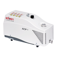
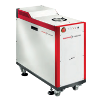
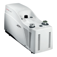
Pumping Principle: The ATHM pump uses a multi-staged turbomolecular pump with a spiral helix molecular drag section, providing high pumping speeds and ultimate vacuum, and extended forevacuum tolerance. Hybrid Turbopump in an Installation: The pump exhaust gases are evacuated to atmosphere by a primary pump. The ATHM compression ratio is set by the design. Built-in Heater Band (on MT model): At high pressure and high throughput processes such as metal etch, deposit can build up in the lower compression stages of the rotor, leading the pump to early failure. The built-in heater band allows pump heating up to 75 °C, which is sufficient to avoid the condensation effect. The device is controlled by the controller. The MT version must be equipped with its water valve. Back-up Ball Bearings: Dry-lubricated ceramic ball bearings are used. They are not used in normal operation, since the rotor is not in contact with the ball bearings. They protect the pump in accidental air in-rushes, accidental shocks, or power failure. No Maintenance: The pump design does not include parts liable to wear and doesn't need preventive maintenance. However, the back-up ball bearings used in case of accidental shut-downs have to be changed when the controller indicates it. Battery Free: In case of a power failure, the pump motor acts like a generator, supplying enough power for the magnetic bearings. When the rotation speed is too low, the pump shuts down and lands on the back-up ball bearings. Variation of the Pump Rotational Speed: The ATHM pump rotation speed can be selected and set between a minimum speed and the maximum speed. This allows optimizing pumping characteristics according to customer application (e.g., high pressure pumping). A distinction is made between the following speeds: reduced speed (STANDBY speed), which can be set between the low speed value and the nominal speed, and nominal speed, preselected at factory. Controller: The ATH 2800 M/MT and ATH 3200 M/MT pumps work with an OBC controller or with the MAGPOWER controller.
Installation:
General Maintenance:
Maintenance Frequency:
Specific Maintenance Instructions:
Service and Support: Pfeiffer Vacuum offers first-class customer service, including on-site maintenance, overhaul/repair in the nearby Service Location, fast replacement with refurbished exchange products, and advice on the most cost-efficient and quickest solution. Detailed information and addresses are available on the Pfeiffer Vacuum website. Sending of contaminated pumps or devices: No devices will be accepted if they are contaminated with micro-biological, explosive or radioactive substances. Hazardous substances are substances and compounds in accordance with the hazardous goods regulations. The customer must neutralize the pump by flushing it with nitrogen or dry air, close all openings airtight, seal the pump or device in suitable protective film, and return the pump/device only in a suitable and sturdy transport container.
| Brand | Pfeiffer Vacuum |
|---|---|
| Model | ATH 2800 MT |
| Category | Water Pump |
| Language | English |