Do you have a question about the Pfeiffer Vacuum DCU 002 and is the answer not in the manual?
Details the scope and applicability of the operating instructions and product variants.
Identifies authorized personnel for product handling, including transport, installation, and operation.
Explains document conventions like instructions, pictographs, stickers, and abbreviations.
Defines the structure for action steps, including individual and multi-part sequences.
Explains the meaning of pictographs used to convey important information within the document.
Describes product stickers, their placement, and their significance for identification and certification.
Provides a list of abbreviations used in the document with their corresponding meanings.
Outlines the risk levels (DANGER, WARNING, CAUTION, NOTICE) and information level used in the document.
Details safety instructions regarding electrical shock hazards during installation and general usage.
Provides general safety precautions for handling the product, including electrical safety and modifications.
Specifies environmental and operational limits like air pressure, altitude, humidity, and temperature.
Defines the intended use of the DCU for controlling electronic drive units and vacuum pumps.
Lists improper uses that invalidate warranty, such as incorrect connections or operation in hazardous areas.
Explains how to identify the product using rating plate information for clear communication.
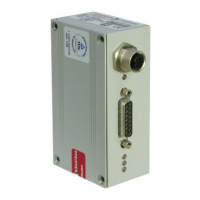
Details features of different DCU models, including power supply, input, and drive unit compatibility.
Lists the items included in the shipment for the Display and control unit DCU.
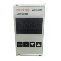
Describes the DCU's role as a display and control unit for vacuum pumps and pressure measurement.
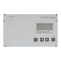
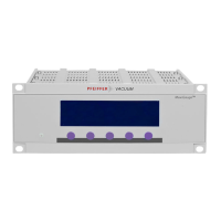
Explains the user interface of the DCU, comprised of four short-stroke keys (softkeys).
Visualizes current operating conditions of connected devices using symbols under the LC-display.
Provides general comments and steps for preparing the site and installing the device upright.
Details the procedure for installing the device in a 19" rack, considering overheating risks.
Covers connecting the electrical supply, including safety warnings for electric shock and installation errors.
Presents connection diagrams for DCUs with and without integrated power supply packs.
Describes how to establish the mains connection for DCUs with integrated power supply packs.
Explains how to connect Pfeiffer Vacuum transmitters using the 'X3' socket.
Explains how parameters are programmed into the drive unit and accessed via displays or RS-485.
Details additional parameters available in DCUs for controlling external components like measuring instruments.
Describes the various data types used for parameters, including their format and examples.
Explains the 4-line LC-display and its functions for visualizing parameters and equipment status.
Details the procedure for switching on the DCU, including self-test and readiness indication.
Guides on selecting, displaying, and configuring parameters using the DCU keys and interface.
Explains the meaning of the LED indicators on the front panel for basic operating statuses.
Provides procedures for switching off the DCU 002 and DCUs with integrated power supply packs.
Describes how vacuum pump and drive unit malfunctions are indicated via warning or error messages on the DCU.
Lists device-specific warning and error messages, including handling procedures and remedies.
Outlines requirements and procedures for sending contaminated products for service.
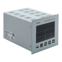
Presents technical specifications for DCU 002, DCU 110, DCU 180, DCU 310, and DCU 400.
Provides dimension drawings in millimeters for DCU 002, DCU 110, and DCU 180, 310, 400 models.
| Category | Control Unit |
|---|---|
| Manufacturer | Pfeiffer Vacuum |
| Model | DCU 002 |
| Power Supply | 24 V DC |
| Display | LCD |
| Protection Class | IP40 |
| Type | Control Unit |
| Communication Interfaces | RS-485 |
| Operating Temperature | 0 °C to +50 °C |
| Storage Temperature | -20 °C to +70 °C |