Do you have a question about the Pfeiffer Vacuum TC 1200 and is the answer not in the manual?
Information on the manual's applicability and current state.
Explanation of symbols, instructions, and abbreviations used.
Guidelines for understanding hazard levels and safety symbols.
Explanation of graphic symbols used in safety instructions.
Explanation of text conventions for commands and notes.
List of acronyms and their meanings.
Essential safety measures for installation and operation.
Guidelines for correct and intended usage of the unit.
Definition of misuse and consequences for warranty.
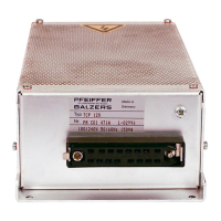
Details on the unit's name, model, and key characteristics.
Specifies the ambient conditions for installation and operation.
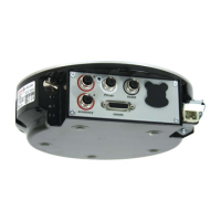
Overview of the electronic drive unit's operational purpose.
Description of the interface ports and their general functions.
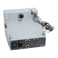
Instructions and safety warnings for electrical connection.
Details on connecting accessories via M12 sockets.
Description of the D-sub connector for remote control.
Information on the PV.can interface for measurement and service.
Details on the RS-485 interface for control units or PC.
Detailed pin configuration for the remote control connector.
Description of the +24V DC output and its use with digital inputs.
Explanation of digital inputs for controlling unit functions.
Description of digital and analog outputs for status signals.
Details on the functionality of the relay contacts.
Information on connecting to the RS-485 interface.
Interface specifications and electrical isolation for RS-485.
Guidance on connecting external control devices or PCs.
Instructions for creating bus systems using the RS-485 connection.
Introduction to parameters and their use with drive units.
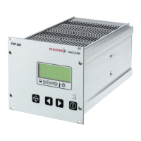
Explanation of parameter structure, display, and access methods.
List and description of commands to control pump functions.
Queries for obtaining operational status information.
Parameters for configuring operational set points and thresholds.
Steps to configure accessory connections using parameters.
Parameter options for configuring accessory inputs/outputs.
Configuration of digital outputs and relay functions for remote operation.
Configuration options for digital inputs via the remote interface.
Mapping of parameters to analog output signals.
Configuration of analog inputs for setting parameters.
Selection of communication interfaces for control.
Using parameters to manage pump operation and settings.
Default pre-programmed settings for immediate operation.
Procedure for verifying parameter suitability before operation.
Configuring gas modes for optimal performance and safety.
Adjusting the power consumption setting and its effect on run-up time.
Troubleshooting prolonged pump start-up times.
Configuring signals based on rotation speed thresholds.
Reducing rotation speed and throughput for specific processes.
Using standby mode to reduce rotation speed during stops.
Confirming nominal rotation speed for safety.
Configuring backing pump operation modes.
Setting backing pumps to standby via digital output.
Controlling connected accessories like heating and sealing gas.
Options for venting the turbopump after operation.
Using temperature thresholds for safe shutdown.
Procedures for starting and stopping the turbopump.
Structure and characters of RS-485 communication telegrams.
Examples of data requests, control commands, and responses.
Illustrates data request and response for actual rotation speed.
Demonstrates control commands for pump station and acknowledgments.
Explanation of data types used in the RS-485 protocol.
Overview of how malfunctions are indicated and handled.
Meaning of LED indicators on the drive unit.
List of error codes, possible causes, and remedies.
DCU-specific error messages and their troubleshooting.
| Brand | Pfeiffer Vacuum |
|---|---|
| Model | TC 1200 |
| Category | DC Drives |
| Language | English |