Do you have a question about the Pfeiffer DCU 001 and is the answer not in the manual?
Details symbols, abbreviations, and position numbers used in the manual for user orientation.
Covers DCU definition, scope of delivery, mechanical design, and connection options for PFEIFFER drive units.
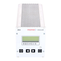
Details the operating and display elements on the front of the DCU unit.
Describes the connections and components on the rear of the DCU unit.
Covers safety precautions and environmental conditions required before installing the DCU unit.
Provides guidelines for fitting the DCU units into a 19”/3HE rack with proper ventilation.
Illustrates the connection diagrams for DCU units with and without a power unit.
Details the procedure for making mains and electronic drive unit connections for DCU units.
Provides a brief overview of operating the DCU, including parameter selection and setting.
Explains that functional aspects are illustrated as parameters, readable and modifiable via keyboard.
Details the procedure for switching on DCU 001 and DCU 100-600, including the self-test process.
Explains the functions of the four keys on the front panel for parameter control and station operation.
Describes the four-line LC display functions for parameter display, values, and error messages.
Provides a table defining symbols used for pump status, pre-selection, stand-by, and temperature.
Explains the conditions of the red (error) and green (operation) LEDs on the front panel.
Details the use of the serial interface RS 485 for connecting the pump controller to the vacuum pump.
Describes general error handling, including shutdown causes and recovery procedures after error removal.
Lists errors that can occur during self-testing and provides possible actions or service contacts.
Presents a data list with connection voltage, frequency, power consumption, and weight for DCU models.
Provides dimensional drawings and specific measurements for DCU 001, DCU 100-300, and DCU 600 units.
