Pfeiffer Chemie-Armaturenbau GmbH
Pfeiffer Chemie-Armaturenbau GmbH • Phone: +49 2152 2005-0 • Fax: +49 2152 1580 • E-Mail: vertrieb@pfeiffer-armaturen.com • Internet: www.pfeiffer-armaturen.com
2 of 4
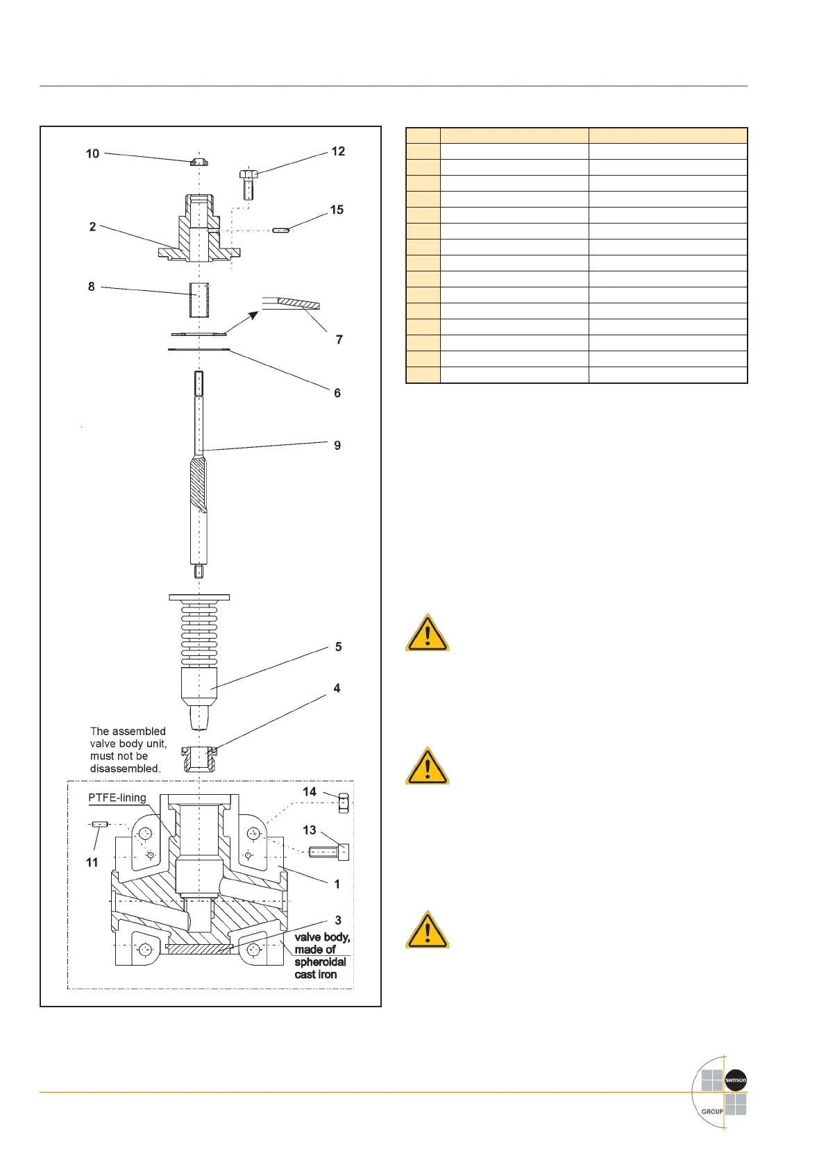
Item Description Material
1 Body with casing EN-JS 1049 (GGG 40.3)
2 Bonnetr fl ange 1.0037
3 Bottom fl ange 1.0037
4 Seat PTFE
5 Bellows unit with plug PTFE
6 Thrust washer 1.4305
7 Spring washer 1.8159
8 Bushing Glycodur
9 Stem connector 1.4571
10 Wiper ring Buna
11 Grooved pin 1.4301
12 Screw A2-70
13 Screw A2-70
14 Nut A2-70
15 Grooved pin 1.4301
Table 1 - Parts list
3. The assembly of a micro valve
3.1 Preparation for assembly
To assemble the control valve, fi rst clean all parts thoroughly,
and lay them on a soft padded surface ( rubber mat) or simi-
lar.
Take into consideration, that parts made of plastic are gener-
ally soft and sensitive, in particular the sealing surfaces must
handled with care, and not be damaged.
Attention: To avoid cold corrosion of the screws
in the bodies, the manufacturer has used a high
performance lubricating grease (i.e. Gleitmo 805.
from Fuchs).
This grease however, may not be applied to valves, which are
used in an oxygen environment. Valves which must be free of
grease, especially for use in oxygen, an appropriate lubrica-
tion must be used.
Note: The position and arrangement of the individu-
al parts shown in the explosion drawing (Fig. 3) must
be observed when assembling the valve.
3.2 Pre-assembly of the spindel unit
Apply grease to lower threaded end of the single unit stem.
( 9 )
Note: With the single versions, the stem consists of
three single parts. With a retainer ring, the guide is
pre-assembled with the stem.
The pre-assembled bellow unit ( 5 ) with the thread insert and
plug, is screwed tightly onto the guide stem. ( 9 )
( Due to a slide tendency of PTFE when the bellow unit is
screwed onto the stem, the use of a sandpaper lining has
proven to help avoid sliding.)
Fig. 3 - Explosion drawing of a micro-fl ow valve Series 6a

 Loading...