
 To Next Page
N
nicole37Aug 2, 2025
What to do if the Pfeiffer TPG 261 shows a main memory (RAM) error?
- JJoan BaxterAug 2, 2025
If you're seeing a main memory (RAM) error on your Pfeiffer Control Unit, acknowledge it with the key.

What to do if the Pfeiffer TPG 261 shows a main memory (RAM) error?
If you're seeing a main memory (RAM) error on your Pfeiffer Control Unit, acknowledge it with the key.
What to do if the Pfeiffer TPG 261 displays a program memory (EPROM) error?
If your Pfeiffer Control Unit displays a program memory (EPROM) error, acknowledge it with the key.
What to do if the Pfeiffer Control Unit displays a parameter memory (EEPROM) error?
If the Pfeiffer Control Unit is showing a parameter memory (EEPROM) error, acknowledge the error with the key.
What to do if the Pfeiffer TPG 261 Control Unit displays a display driver error?
If you encounter a display driver error on your Pfeiffer Control Unit, acknowledge it with the key.
What to do if the Pfeiffer TPG 261 Control Unit displays an A/D converter error?
If your Pfeiffer Control Unit is showing an A/D converter error, acknowledge it with the key.
What to do if the Pfeiffer TPG 261 displays an operating system (Task Fail) error?
If the Pfeiffer Control Unit displays an operating system (Task Fail) error, acknowledge it with the key.
Document applicability, firmware version, and change notes.
Explains warning symbols and indicators used in the manual.
Specifies requirements for personnel operating the equipment.
Provides essential safety precautions and warnings.
Details electrical input specifications like voltage, frequency, and power.
Specifies operating and storage conditions like temperature and humidity.
Lists gauges compatible with the TPG 261 unit.
Details front panel and remote control operations.
Lists key measurement parameters and their values.
Specifies requirements for personnel performing installation.
General instructions for installing and setting up the TPG 261.
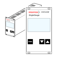
Describes the front panel layout and controls of the TPG 261.
Instructions for powering the unit on and off.
Outlines the different operating modes of the TPG 261.
Details on setting and editing switching function thresholds.
How to display, enter, and edit parameters for the connected gauge.
Selecting the unit for measured values (mbar, Torr, Pascal).
Setting the baud rate for RS232C interface.
Describes communication via the RS232C serial interface.
Details data format, bits, parity, and handshake for RS232.
Setting and allocating threshold values for switching functions.
Setting measurement value filter and time constants.
Selecting the unit for measured values (mbar, Torr, Pascal).
Setting the baud rate for RS232C interface.
Instructions on how to clean the exterior of the unit.
Explains error indicators and the error relay.
Lists common error messages, causes, and remedies.
Precautions for proper storage to prevent damage.
Guidelines for environmentally safe disposal of product parts.
Conversion factors for pressure units.
Steps to prepare the unit for firmware update.
 General
| Input Voltage | 24 V DC |
|---|---|
| Communication Interface | RS-232, RS-485 |
| Temperature Range | 0 - 50 °C |
| Dimensions | 100 x 100 x 60 mm |
| Display | LCD |
| Power Supply | 24 V DC |
| Display Digits | 4 |
| Operating Temperature | 0 - 50 °C |
| Storage Temperature | -20 - 70 °C |
| Protection Class | IP40 |
| Outputs | Analog, Digital |
| Weight | 0.5 kg |