BG 5195 BEN / A (2011-05) TPG261.oi 21
This connector allows to read the measuring signal, to
evaluate the state of the floating contacts of the error
relay, and to activate or deactivate the gauge (→ 47).
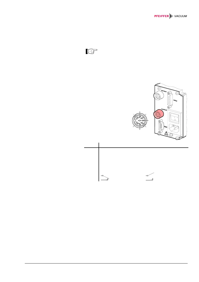
Connect the peripheral components to the
control connector on the rear of the unit using
your own, screened (electromagnetic compati-
bility) cable.
Pin assignment of
the female 7-pin
Amphenol C91B ap-
pliance connector:
1
3
2
54
67
8
64
7
5
2
1
3
Pin Signal
2
5
4
1, 6
Analog output gauge 0 … +10 VDC
Screening GND
Gauge on signal ≤+0.8 VDC
off signal +2.0 … 5 VDC or input open
Not assigned
3
7
No error
Error or power
supply turned off
A suitable connector is supplied with the TPG 261.
3.5 control Connector
Pin assignment
Contact positions
control