EasyManua.ls Logo

Pfeiffer Series 6a User Manual

Pfeiffer Series 6a
4 pages
To Next Page IconTo Next Page
Page #1 background imageLoading...
Page #1 background image
Pfeiffer Chemie-Armaturenbau GmbH • Phone: +49 2152 2005-0 • Fax: +49 2152 1580 • E-Mail: vertrieb@pfeiffer-armaturen.com • Internet: www.pfeiffer-armaturen.com
1 of 4
This equipment may only be dismounted and disas-
sembled by skilled staff, who are familar with the as-
sembly, start-up and the operation of this product.
Skilled staff in the sense of these repair and assembly instruc-
tions, are persons who, as a result of their training, knowledge,
and experience, also their knowledge of the relevant standards,
are able to reconise possible dangers.
1. Design, operation and dimensions
Design, operation and dimensions, as well as all further technical
details can be found in the Data sheet < TB 06a_EN >
2. Installation, start-up and maintenance
Guidelines for the installation, start-up and maintenance can be
found in the respective operating instructions
< BA 01a-01_EN > for automatic control valves, i.e.
< BA 01a-02_EN > for manually operated control valve,
Fig. 2 - Sectional view of a micro- ow valve, Series BR 6a => Parts list, see Table 1 on page 2
Repair instructions
Micro-flow Valve Series 6a
Fig. 1 - Micro- ow valve Series 6a with Samson control actuator
0. Introduction
These instructions are intended to support the user in
the assembly and repair of micro- ow valves of the
series 6a.
Technical details, as a result of further development of
the valves mentioned in these instructions are subject to
modi cation.
The text and illustrations do not necessarily display the
scope of supply, or an eventual order of spare parts.
Drawings and graphics are not to scale.
Customer related designs, which are not in accordance
with our standard offer, are not shown.
The transfer of these instructions to third parties is only
allowed with the written approval of Pfeiffer Chemie-
Armaturenbau GmbH.
All documents are protected according to the laws of
the German Copyright Act.
Question and Answer IconNeed help?

Do you have a question about the Pfeiffer Series 6a and is the answer not in the manual?

Pfeiffer Series 6a Specifications

General IconGeneral
BrandPfeiffer
ModelSeries 6a
CategoryControl Unit
LanguageEnglish

Summary

0. Introduction

1. Design, Operation, and Dimensions

2. Installation, Start-up, and Maintenance

3. The Assembly of a Micro Valve

3.1 Preparation for Assembly

Clean all parts thoroughly and lay them on a soft padded surface before assembly.

3.2 Pre-assembly of the Spindel Unit

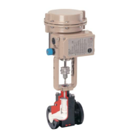
Apply grease to the lower threaded end of the single unit stem and screw the pre-assembled bellow unit onto the stem.

3.3 Pre-assembly of the Bonnet Flange

Press the glycodur bushing into the bonnet flange and insert the pre-assembled stem unit.

3.4 Pre-assemble of the Valve Body

Assemble the valve body, PTFE-liner, and bonnet flange using grooved pins and screws.

3.5 Final Assembly of the Valve

Clamp the body in a vice, place the bonnet flange carefully onto the body, and tighten screws evenly.

3.6 Stroke Adjustment

Adjust the dimension 'A' from the stem shaft nut to the shell top according to table 2.

3.7 Stroke Limit

Set stroke limit to 10 mm for specific operation modes using a spacing washer.

4. Trouble Shooting

5. Repair of the Micro Valve

5.1 Replacing the Bellow Unit and the Wipe Off Ring

Check seals and bellow unit for defects if leakage occurs; dismantle and replace as needed.

5.2 Other Repairs

Larger repairs should be carried out by skilled personnel at the Pfeiffer factory.

Related product manuals