308F
OFFICIAL RADIOpplement SERVICE MANUAL
Su
No. 5
PHILCO RADIO & TELEVISION CORP.
PHILCO
Service Bulletin-No. 140
Model 8 0
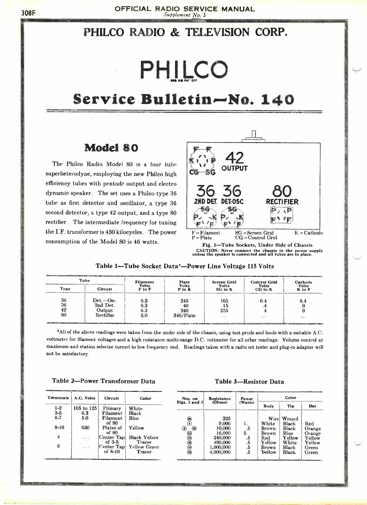
The Philco Radio Model 80 is a four tube
superheterodyne, employing the new Philco high
efficiency tubes with pentode output and electro
dynamic speaker. The set uses a Philco type 36
tube as first detector and oscillator, a type 36
second detector, a type 42 output, and a type 80
rectifier.
The intermediate frequency for tuning
the I.F. transformer is 450 kilocycles. The power
consumption of the Model 80 is 46 watts.
42
OUTPUT
36 36
2ND DET. DET:OSC.
/-SSIN
K
,,E%
,E /F.,
80
RECTI FIER
/
11
Fs
IF
F = Filament
SG =Screen Grid
K = Cathode
P = Plate CG = Control Grid
Fig. 1-Tube Sockets, Under Side of Chassis
CAUTION: Never connect the chassis to the power supply
unless the speaker is connected and all tubes are in place.
Table 1-Tube Socket Data*-Power Line Voltage 115 Volts
Tube
Filament Plate
Screen Grid
Control Grid
Cathode
Volts
Volts
Volts
Volts Volts
Type
Circuit
F to F
P to K SG to K
CG to K K to F
36
Det.-Ose.
6.3
245 165 6.4
8.4
36
2nd Det.
6.3 40 15 .4
0
42
Output
6.3
240 255 4
0
80
Rectifier
5.0
340/Plate
. ..
...
...
*All of the above readings were taken from the under side of the chassis, using test prods and leads with a suitable A.C.
voltmeter for filament voltages and a high resistance multi -range D.C. voltmeter for all other readings. Volume control at
maximum and station selector turned to low frequency end. Readings taken with a radio set tester and plug-in adapter will
not be satisfactory.
Table 2-Power Transformer Data
Terminals
A.C. Volts
Circuit
Color
1-2
105 to 125
Primary
White
3-5
6.3 Filament
Black
6-7
5.0
Filament
of 80
Blue
8-10
630
Plates of
of 80
Yellow
4
..
.
Center Tap
of 3-5
Black Yellow
Tracer
9
..
.
Center Tap
of 8-10
Yellow Green
Tracer
Table 3-Resistor Data
Nos. on
Figs. 2 and 3
Resistance
(Ohms)
Power
(Watts)
Color
Body Tip Dot
I
325
9,000
1.Wire
White
Wound
Black Red
® ®
10,000
.5 Brown
Black Orange
®
16,000
5. Brown
Blue Orange
®
240,000
.5
Red Yellow Yellow
490,000
.5
Yellow White
Yellow
I
1,000,000 .5
Brown Black
Green
4,000,000
.5 Yellow
Black
Green
 Loading...