OFFICIAL RADIO SERVICE MANUAL
Supplement No. 5
308G
p
PHILCO RADIO & TELEVISION CORP.
PH I LCO
U& MT. OM
Service Bulletin No. 120C
THIS BULLETIN SUPERSEDES SERVICE BULLETINS NOS. 120 AND 120 B
Adjusting Philco Superheterodynes
The compensating condensers in every Philco Receiver are carefully adjusted before the set leaVes
the factory.
Under ordinary circumstances they should never have to be re -adjusted in the field.
Extremely rough handling during shipment, or a slight change in some of the electrical characteristics
of the radio circuit may in some cases make re -adjustment necessary.
The indications that the set may require re -adjustment are poor sensitivity, poor selectivity and
dial readings in kilocycles off more than 20 K.C. In some cases, an unstable condition of the set with
a tendency to squeal or howl on certain sections of the dial may also be an indication of improper
adjustment.
Under no circumstances should a re -adjustment be attempted unless the
necessary equipment is
available and unless the proper instruction has been received.
Your distributor will gladly assist you
in both of these matters.
The general method of adjusting the compensating condensers in all Philco superheterodyne
receivers is the same.
Once this procedure is understood for one model, it can be applied with but
little change to the various other Philco models. By means of the instructions below and by reference
to the different illustrations, the complete adjustments can be made on all Philco superheterodynes.
EQUIPMENT. The following equipment is needed:
1.
Philco Model 095 Intermediate Frequency Oscillator accurately calibrated at 175 K. C. and 260
K. C., equipped with self contained output meter and batteries.
2.
Philco fibre wrench, part 3164.
INTERMEDIATE FREQUENCY OR I. F. ADJUSTMENTS. The adjustment of the I.
F.
compensating condensers should be done in the following manner:
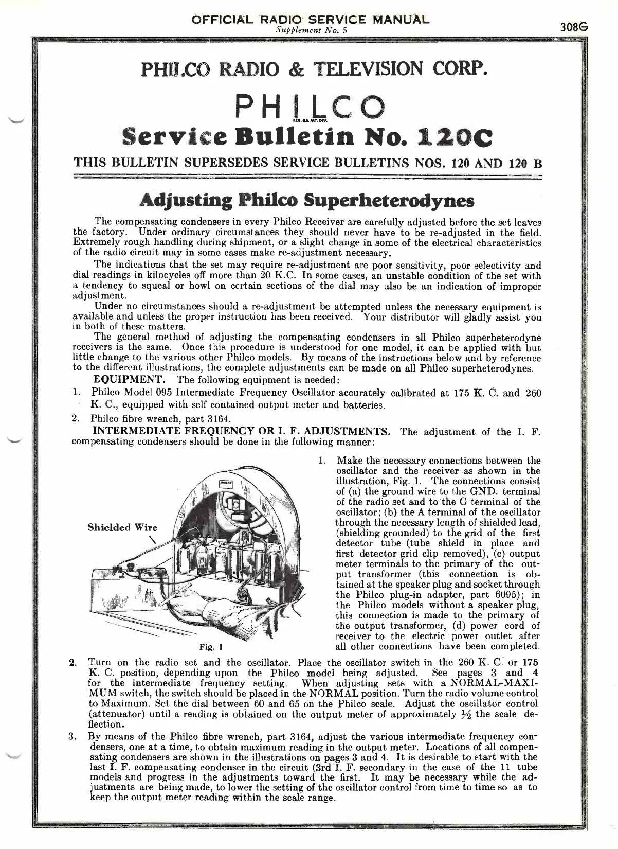
Shielded Wire
Fig. 1
1.
Make the necessary connections between the
oscillator and the receiver as shown in the
illustration, Fig. 1.
The connections consist
of (a) the ground wire to the GND. terminal
of the radio set and to the G terminal of the
oscillator; (b) the A terminal of the oscillator
through the necessary length of shielded lead,
(shielding grounded) to the grid of the first
detector tube (tube
shield in place and
first detector grid clip removed), (c) output
meter terminals to the primary of the out-
put transformer (this
connection is ob-
tained at the speaker plug and socket through
the Philco plug-in adapter, part 6095); in
the Philco models without a speaker plug,
this connection is made to the primary of
the output transformer, (d) power cord of
receiver to the electric power outlet after
all other connections have been completed.
2.
Turn on the radio set and the oscillator. Place the oscillator switch in the 260 K. C. or 175
K. C. position, depending upon the Philco model being adjusted.
See pages 3 and 4
for the intermediate
frequency setting.
When adjusting
sets
with a NORMAL -MAXI-
MUM switch, the switch should be placed in the NORMAL position. Turn the radio volume control
to Maximum. Set the dial between 60 and 65 on the Philco scale.
Adjust the oscillator control
(attenuator) until a reading is obtained on the output meter of approximately
the scale de-
!
flection.
3.
By means of the Philco fibre wrench, part 3164, adjust the various intermediate frequency con-
densers, one at a time, to obtain maximum reading in the output meter. Locations of all compen-
sating condensers are shown in the illustrations on pages 3 and 4.
It is desirable to start with the
last I. F. compensating condenser in the circuit (3rd I. F. secondary in the case of the 11 tube
models and progress in the adjustments toward the first.
It may be necessary while the ad-
justments are being made, to lower the setting of the oscillator control from time to time so as to
keep the output meter reading within the scale range.
 Loading...