308H
OFFICIAL RADIO SERVICE MANUAL
Suplement No.
PHILCO RADIO & TELEVISION CORP.
4.
After these adjustments have been completed,
remove the oscillator connection from the grid
terminal of the first detector tube and restore the grid clip connection
to this terminal.
5.
The adjustment of the first I. F. primary (coupling) condenser
may have a slight effect on
the adjustment of the low frequency compensating condenser in the Philco
models which have
a combined oscillator and first detector tube ---such as the
51 and
52
series, the latest 70 and
90 series, and the 71, 91,
15
and 47
series. After making the adjustment of the I. F condensers
on these models, be sure to make the low frequency adjustment as described below.
HIGH FREQUENCY ADJUSTMENTS. Improper adjustment of the
high frequency com-
pensating condenser is characterized by weak reception and
poor selectivity at the high frequency
end of the dial and by dial readings being off by
more than
20 K.
C. at this end of the dial.
Proceed
in the following manner:
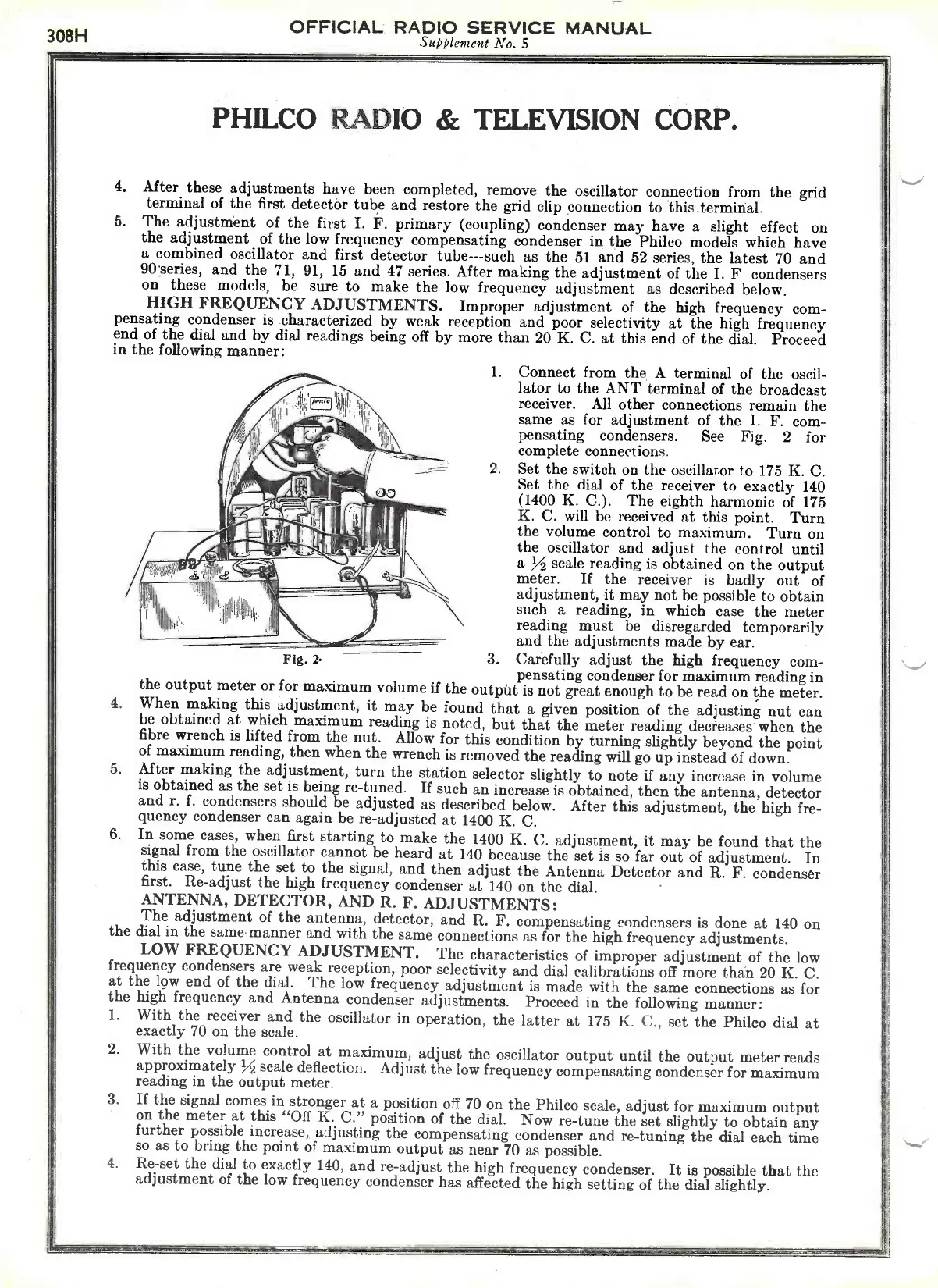
1.
Connect from the A terminal of the oscil-
lator to the ANT terminal of the broadcast
receiver.
All other connections remain the
same as for adjustment of the I. F. com-
pensating
condensers. See
Fig.
2
for
complete connections.
2.
Set the switch on the oscillator to
175 K. C.
Set the dial of the receiver to exactly 140
(1400 K.
C.).
The eighth harmonic of
175
K.
C. will be received at this point.
Turn
ilVEr
the volume control to maximum. Turn on
1110
_cjia
the oscillator and adjust the control until
.111
a
scale reading is obtained on the output
meter.
If the receiver
is badly out of
adjustment, it may not be possible to obtain
1111 h
such a reading, in which case the meter
ydireading must be disregarded temporarily
and the adjustments made
Fig. y
3.
Carefully adjust the high frequency com-
pensating condenser for maximum reading in
the output meter or for maximum volume if the
output is not great enough to be read on the meter.
4.
When making this adjustment, it
may be found that a given position of the adjusting nut
can
be obtained at which maximum reading is noted,
but that the meter reading decreases when the
fibre wrench is lifted from the nut.
Allow for this condition by turning slightly beyond
the point
of maximum reading, then when the wrench is removed
the reading will go up instead of down.
5.
After making the adjustment, turn the station
selector slightly to note if any increase in volume
is obtained as the set is being re -tuned.
If such an increase is obtained, then the antenna, detector
and r. f. condensers should be adjusted
as described below.
After this adjustment, the high fre-
quency condenser can again be re -adjusted at 1400
K. C.
6.
In some cases, when first starting to make the
1400
K.
C. adjustment, it may be found that the
signal from the oscillator cannot be heard at 140
because the set is so far out of adjustment.
In
this case, tune the set to the signal, and then
adjust the Antenna Detector and R. F. condenser
first. Re -adjust the high frequency condenser
at 140 on the dial.
ANTENNA, DETECTOR, AND R. F. ADJUSTMENTS:
The adjustment of the antenna, detector, and R.
F. compensating condensers is done at 140 on
the dial in the same manner and with the
same connections as for the high frequency adjustments.
LOW FREQUENCY ADJUSTMENT. The
characteristics of improper adjustment of the low
frequency condensers are weak reception,
poor selectivity and dial calibrations off more than 20
K. C.
at the low end of the dial.
The low frequency adjustment is made with the
same connections as for
the high frequency and Antenna condenser adjustments.
Proceed in the following manner:
1.
With the receiver and the oscillator in operation, the
latter at
175 K.
C., set the Philco dial at
exactly
70
on the scale.
2.
With the volume control at maximum, adjust
the oscillator output until the output meter reads
approximately M scale deflection.
Adjust the low frequency compensating condenser for
maximum
reading in the output meter.
3.
If the signal comes in stronger at a position off 70
on the Philco scale, adjust for maximum output
on the meter at this "Off K. C." position of the dial. Now
re -tune the set slightly to obtain any
further possible increase, adjusting the compensating
condenser and re -tuning the dial each time
so as to bring the point of maximum output as near
70
as possible.
4.
Re -set the dial to exactly 140, and re -adjust the high
frequency condenser.
It is possible that the
adjustment of the low frequency condenser has affected
the high setting of the dial slightly.
 Loading...