EasyManua.ls Logo

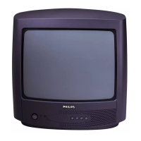
Philips 14PT1501/12 User Manual

Philips 14PT1501/12
78 pages
To Next Page IconTo Next Page
Page #1 background imageLoading...
Page #1 background image
Published by JH 0664 BG CD Customer Service Printed in The Netherlands Subject to modification EN 3122 785 16011
©
Copyright 2006 Philips Consumer Electronics B.V. Eindhoven, The Netherlands.
All rights reserved. No part of this publication may be reproduced, stored in a
retrieval system or transmitted, in any form or by any means, electronic,
mechanical, photocopying, or otherwise without the prior permission of Philips.
Colour Television Chassis
TE3.2E
CA
G_16010_000.eps
260406
Contents Page Contents Page
1. Technical Specifications, Connections and Chassis
Overview 2
2. Safety Instructions, Warnings, and Notes 5
3. Directions for Use 7
4. Mechanical Instructions 8
5. Service Modes, Error Codes and Fault Finding 9
6. Block Diagrams, Test Point Overviews, and
Waveforms
Block Diagram Audio / Video 11
Block Diagram Power Supply 12
I2C Diagram 13
Block Diagram 13
7. Circuit Diagrams and PWB Layouts Diagram PWB
Main Panel (05TA085-5): MCU (A1) 16 23-24
Main Panel (05TA085-5): Video (A2) 17 23-24
Main Panel (05TA085-5): Sound (A3) 18 23-24
Main Panel (05TA085-5): Power (A4) 19 23-24
Main Panel (05TA085-5): Deflection (A5) 20 23-24
CRT Panel (05TA085-5) (A6) 21 23-24
Main Panel (05TA085-5): SCART (A7) 25 23-24
Main Panel (05TA085-6): MCU (A1) 25 32-33
Main Panel (05TA085-6): Video (A2) 26 32-33
Main Panel (05TA085-6): Sound (A3) 27 32-33
Main Panel (05TA085-6): Power (A4) 28 32-33
Main Panel (05TA085-6): Deflection (A5) 29 32-33
CRT Panel (05TA085-6) (A6) 30 32-33
Main Panel (05TA085-6): SCART (A7) 31 32-33
Side I/O Panel (21PT5421 only) (A8) 34 35
8. Alignments 37
9. Circuit Descriptions, Abbreviation List, and IC Data
Sheets 39
Abbreviation List 42
IC Data Sheets 43
10. Spare Parts List 51
11. Revision List 78
Question and Answer IconNeed help?

Do you have a question about the Philips 14PT1501/12 and is the answer not in the manual?

Philips 14PT1501/12 Specifications

General IconGeneral
Screen Size14 inches
Display TechnologyCRT
Aspect Ratio4:3
AudioMono
Remote ControlYes
TunerAnalog
TV SystemPAL
InputsComposite

Summary

Technical Specifications, Connections and Chassis Overview

Technical Specifications

Detailed technical specifications including reception and miscellaneous parameters.

Safety Instructions, Warnings, and Notes

Safety Instructions

Essential safety precautions and regulations for performing repairs.

Warnings

Critical warnings about high voltage, ESD, and picture tube discharge.

Practical Service Precautions

Additional practical precautions for safe and effective service procedures.

Service Modes, Error Codes and Fault Finding

Service Modes

Introduction to service modes for TV repair, alignments, and settings.

Fault Tracing Diagram for Power Supply

Diagnostic flowchart for troubleshooting power supply issues.

Table 5-1 Diversity between Main Board Versions

Table detailing component differences and modifications for main boards.

Block Diagrams, Test Point Overviews, and Waveforms

Block Diagram Audio / Video

Functional block diagram illustrating audio and video signal paths.

Block Diagram Power Supply

Block diagram of the power supply unit, showing voltage outputs.

Circuit Diagrams and PWB Layouts

Main Panel (05TA085-5): MCU

Circuit diagram and PWB layout for the MCU section of the main board.

Main Panel (05TA085-5): Video

Circuit diagram and PWB layout for the video processing section.

Main Panel (05TA085-5): Sound

Circuit diagram and PWB layout for the audio processing and amplification sections.

Main Panel (05TA085-5): Power

Circuit diagram and PWB layout for the power supply unit.

Main Panel (05TA085-5): Deflection

Circuit diagram and PWB layout for the vertical and horizontal deflection systems.

CRT Panel (05TA085-5)

Circuit diagram and PWB layout for the CRT display panel.

Main Panel (05TA085-6): Power

Circuit diagram and PWB layout for the power supply (version 6).

Main Panel (05TA085-6): Deflection

Circuit diagram and PWB layout for the deflection system (version 6).

Alignments

Circuit Descriptions, Abbreviation List, and IC Data Sheets

Spare Parts List

Related product manuals