Ij_jeaudio/video input jacks on the bottom panel of the TV are
r direct picture and sound connections between the TV and
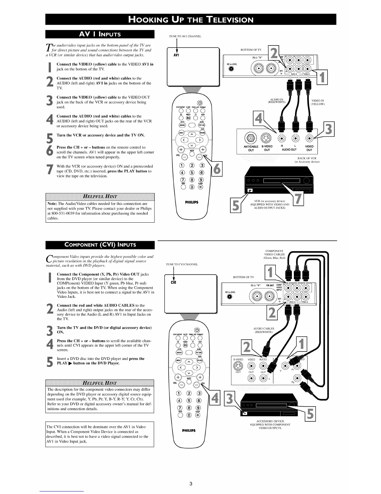
a VCR (or similar device) that has audio/video output jacks.
Connect the VIDEO (yellow) cable to the VIDEO AV1 in
jack on the bottom of the TV.
Connect the AUDIO (red and white) cables to the
AUDIO (left and right) AV1 in jacks on the bottom of the
TV.
Connect the VIDEO (yellow) cable to the VIDEO OUT
jack on the back of the VCR or accessory device being
used.
Connect the AUDIO (red and white) cables to the
AUDIO (left and right) OUT jacks on the rear of the VCR
or accessory device being used.
Turn the VCR or accessory device and the TV ON.
Press the CH + or - buttons on the remote control to
scroll the channels. AV 1 will appear in the upper left corner
on the TV screen when tuned properly.
With the VCR (or accessory device) ON and a prerecorded
tape (CD, DVD, etc.) inserted, press the PLAY button to
view the tape on the television.
Note: The Audio/Video cables needed for this connection are
not supplied with your TV. Please contact your dealer or Philips
at 800-531-0039 for information about purchasing the needed
cables.
TUNE TO AVI CHANNEL
AV1
@
STA_IJS_B/JT SLEEP PR08.LIST FORMAT
0000
R/_IlIO A/_H
8÷6o
AUTO SURR.
SURR.
%3
@@®
®®®
@®®
SURF CLOCK
©®®
PHILIPS
BOTTOM OF TV
75 _?
DCin 124V)
AUDIO IN
(RED/WHITE)
@@
AN'I/CABLE S-VIDEO
OUT OUT
R L VIDEO
AUDIO OUT OUT
VCR (or accessory device)
(EQUIPPED WITH VIDEO AND
AUDIO OUTPUT JACKS)
VIDEO IN
(YELLOW)
BACK OF VCR
(or Accessory device)
omponent Video inputs provide the highest possible color and
ictum resolution in the playback of digital signal source
material, such as with DVD players.
Connect the Component (Y, Pb, Pr) Video OUT jacks
from the DVD player (or similar device) to the
COMP(onent) VIDEO Input (Y green, Pb blue, Pr red)
jacks on the bottom of the TV. When using the Component
Video Inputs, it is best not to connect a signal to the AV1 in
Video Jack.
Connect the red and white AUDIO CABLES to theAudio (left and right) output jacks on the rear of the acces-
sory device to the Audio (L and R) AV 1 in Input Jacks on
the TV.
3
Turn the TV and the DVD (or digital accessory device)
ON.
Press the CH + or - buttons to scroll the available chan-
nels until CVI appears in the upper left corner of the TV
screen.
Insert a DVD disc into the DVD player and press thePLAY I_ button on the DVD Player.
The description for the component video connectors may differ
depending on the DVD player or accessory digital source equip-
ment used (for example, Y, Pb, Pr; Y, B-Y, R-Y; Y, Cr, Cb).
Refer to your DVD or digital accessory owner's manual for def-
initions and connection details.
The CVI connection will be dominate over the AV1 in Video
Input. When a Component Video Device is connected as
described, it is best not to have a video signal connected to the
AV 1 in Video Input jack.
TUNE TO CVI CHANNEL
0!
@
STATU_IT SLEEP PROG.U_ FORM_
0000
_10 MCH
AU_ SUR_
GO@
SUR&
®®®
SURF CLOCK
©®®
PHILIPS
COMPONENT
VIDEO CABLES
(Green, Blue, Red)
BOTTOM OF TV
AUDIO CABLES
(RED/WHITE)
S-VIDEO VIDEO
@®
OUT OUT
®
OUT
Y
ACCESSORY DEVICE
EQUIPPED WITH COMPONENT
VIDEO OUTPUTS.
 Loading...