Do you have a question about the Philips 20PHH4109/88 and is the answer not in the manual?
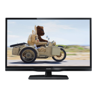
| Display diagonal | 49.5 cm |
|---|---|
| Display Type | LED |
| Resolution | 1366 x 768 pixels |
| Aspect Ratio | 16:9 |
| HDMI Ports | 2 |
| USB Ports | 1 |
| Display technology | LED |
| Screen shape | Flat |
| Response time | 5 ms |
| Contrast ratio (typical) | 3000:1 |
| Display brightness | 200 cd/m² |
| HD type | HD |
| Supported video modes | 720p |
| Digital signal format system | DVB-C, DVB-T |
| RMS rated power | 10 W |
| Number of speakers | 2 |
| SCART ports quantity | 1 |
| Common interface (CI) | Yes |
| Common interface Plus (CI+) | No |
| Electronic Programme Guide (EPG) | Yes |
| VESA mounting | Yes |
| VESA mounting interfaces | 75 x 75 mm |
| Product color | Black |
| Refresh Rate | 60 Hz |
| Built-in Speakers | Yes |
| Power Consumption | 18 W |
| Screen Size | 19.5 inches |
Essential safety guidelines for performing repairs on the TV set.
Critical warnings about electrostatic discharge and high voltage during repair.
Overview of service modes like SAM, Factory, CSM, and ComPair.
Procedure for diagnosing errors using the front LED blinking codes.
General tips for diagnosing and repairing common TV issues.
Steps for performing picture alignments in SAM mode.
Power architecture and details for the TV platform.
Functionality of the main audio and video processor IC.
Internal block diagram of the NT72567BG-BA IC for ADC, DAC, Audio, SIF.
Internal block diagram and pin configuration for the NT78820TL tuner/demodulator IC.
Circuit diagram for the A 715G6163 Power Supply Unit (PSU) AC input.
Circuit diagram for the main power supply section of the PSU.
Circuit diagram for the LED backlight driver.
Circuit diagram for the A 715G6297 Power Supply Unit (PSU).
Circuit diagram for the LED driver within the 715G6297 PSU.
Circuit diagram for the power section of the BA 715G6079 SSB+PSU board.
Circuit diagram for the NT72567's ADC, DAC, Audio, and SIF functions.
Circuit diagram for the STBC and Flash memory interface.
Power distribution circuit diagram for the NT72567 IC.
Circuit diagram for the audio amplifier and headphone output.
Circuit diagram for the DVB-T2/S2 tuner and demodulator.
Circuit diagram for the AC power input and related components.
Circuit diagram for the LED driver power section.
Power circuit diagram for the 715G6094 SSB board.
Circuit diagram for the NT72567's ADC, DAC, Audio, and SIF functions.
Circuit diagram for the STBC and Flash memory interface.
Power distribution circuit diagram for the NT72567 IC.
Circuit diagrams for IR receiver, key input, and tuner.
Circuit diagram for the audio amplifier and headphone output.
Circuit diagram for the DVB-T2/S2 tuner and demodulator.
Circuit diagram for the IR receiver and LED panel.
Circuit diagram for the Control Board with IR/LED panel.