Do you have a question about the Philips 22PFT4031/12 and is the answer not in the manual?
Details the history of changes and updates made to the service manual.
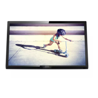
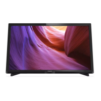
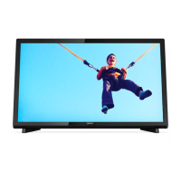
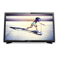
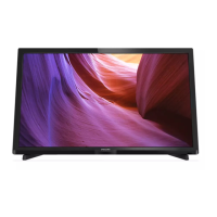
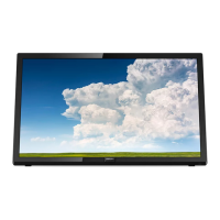
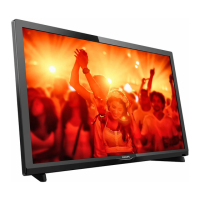
Provides detailed technical specifications and model diversity information for the TV.
Illustrates and describes all rear and side connectors available on the TV set.
Outlines essential safety procedures and precautions for TV repair.
Highlights critical warnings regarding ESD, high voltage, and component handling.
Provides notes on measurements, tools, soldering, and component identification.
Comprehensive list of abbreviations used throughout the service manual.
Details cable routing for various TV models, showing internal component connections.
Specifies safe placement of TV sets for servicing to prevent damage.
Guides for disassembling and removing parts across different TV series models.
Instructions for reassembling the TV set after repairs, emphasizing correct cable placement.
Explains different service modes like SAM, Factory, and CSM for diagnosis and alignment.
Step-by-step guide for updating TV main software via USB for improved performance.
Explains how to read and interpret error codes stored in the NVM for troubleshooting.
Method to display error codes using the front LED when OSD is not functional.
General advice and specific tips for diagnosing and fixing TV issues.
Specifies conditions for performing electrical adjustments and measurements during alignment.
Guides on adjusting white balance, display settings, and color parameters via SAM mode.
Explains how to manage IC communication settings and option codes in NVM for TV configuration.
Procedures for resetting NVM and configuring a repaired SSB, including MAC address reload.
Explains the rule for defining cable position numbers based on connector numbers.
Introduces the TPN16.3E LA chassis, its features, and key components.
Details the TV's power supply architecture, unit specifications, and diversity in display types.
Explains the function and voltages supplied by on-board DC/DC converters.
Covers analog TV and digital DVB-T/C/ISDB-T and DVB-S(2) front-end applications.
Describes the HDMI input configuration and its supported features.
Explains the integrated SoC's video and audio processing capabilities.
Provides block diagrams and pin configurations for the NT72562 IC.
Details block diagram and pin configuration for the T2/S2 Tuner IC.
Provides block diagram and pin configuration for the AD87588 audio amplifier IC.
Details block diagram and pin configuration for the AD22650 Bluetooth IC.
Illustrates the overall system architecture and data flow between major components.
Contains detailed circuit diagrams and PWB layouts for various PSU models.
Details circuit diagrams for different sections of the SSB, including power and interfaces.
Provides circuit diagrams for T2/S2 tuner modules and associated components.
Details the circuit for speaker amplification and headphone output.
Illustrates the circuit diagram for the SCART connector and its signal routing.
Shows the circuit diagram for the VGA input port and PC/DVI audio.
Details the LVDS interface circuit for panel connections and related signals.
Provides circuit diagrams for the AmbiLight and Bluetooth modules.
Details the circuit diagrams for IR, LED, and light sensor components.
Illustrates the circuit diagram for the keyboard control panel and its switches.
Exploded views and part lists for styling components of 4031 series 22" and 24" models.
Exploded views and part lists for styling components of the 5231 series 24" model.
Exploded views and part lists for styling components of 4131 series 32", 43", 49" models.