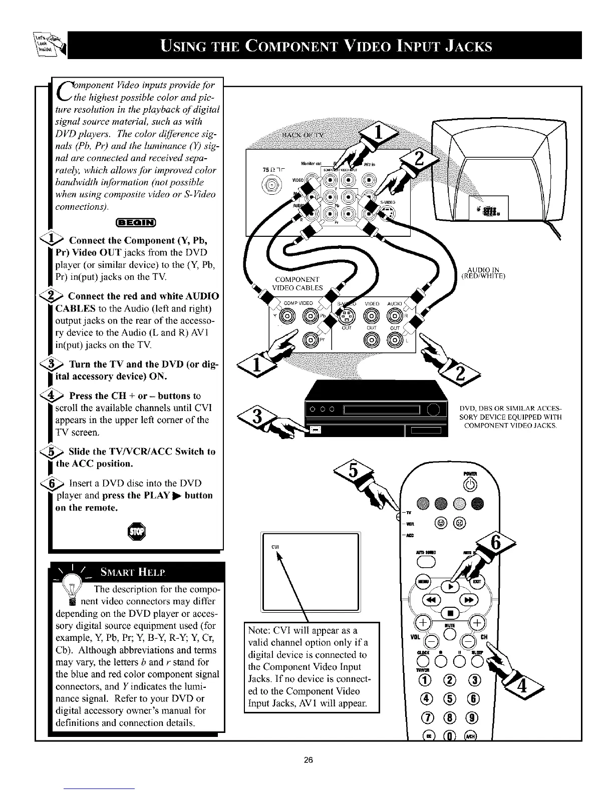
-- f-_omponentVideo inputs providejbr
the highest possible color and pic-
ture resolution in the playback of digital
signal source material, such as with
DVD players. The color d![]krence sig-
nals (Pb, Pr) and the luminance (Y) sig-
nal are connected and received sepa-
rately, which allows jbr improved color
bandwidth ir![brmation (not possible
when using composite video or S-Video
connections).
<_ Connect the Component (Y, Pb,
I Pr) Video OUT jacks from the DVD
player (or similar device) to the (Y, Pb,
Pr) in(put)jacks on the TV.
<_ Connect the red and white AUDIO
I CABLES to the Audio (left and tight)
output jacks on the rear of the accesso-
ry device to the Audio (L and R) AVI
in(put) jacks oll the TV.
<_ "lhrn the TV and the DVD (or dig-
ital accessory device) ON.
_ Press the CH + or - buttons to
scroll the available channels until CVI
I appears in the upper left comer of the
I TV screen.
<_ Slide the TV/VCR/ACC Switch to
I the ACC position.
_ insert a DVD disc into the DVD
player and press the PLAY 1_-button
on the remote.
The description for the compo-
! nent video connectors may differ
depending on the DVD player or acces-
sory digital source equipment used (for
example, Y, Pb, Pr; Y, B-Y, R-Y; Y, Cr,
Cb). Although abbreviations and terms
may vary, the letters b and r stand for
the blue and red color component signal
connectors, and Y indicates the lumi-
nance signal. Refer to your DVD or
digital accessory owner's manual for
definitions and connection details.
k
Note: CVI will appear as a
valid channel option only if a
digital device is connected to
the Component Video Input
Jacks. If no device is connect-
ed to the Component Video
input Jacks, AV 1 will appear.
AUDIO IN
(RED/WHITE)
DVD, DBS OR SIMILAR ACCES-
SORY DEVICE EQUIPPED WITH
COMPON ENT VIDEO JACKS
@@@®
@@
®@@
26