Static Center Convergence Adjustment
1. Apply a center cross or crosshatch pattern to the antenna/cable input terminal and observe the screen to
ensure that the yoke is not tilted. If necessary, rotate the yoke to obtain a level raster.
2. Use the Menu Left/Right keys to select Blue (B), and use the Menu Up/Down keys to set Blue to maximum.
3. Slowly spread, and if necessary, rotate the 4-pole magnetic rings to converge red and blue lines at the
center of the screen.
4. Use the Menu Left/Right keys to select Green (G), and use the Menu Up/Down keys to set Green to
maximum.
5. Slowly spread, and if necessary, rotate the 6-pole magnetic rings to converge red/blue on green lines at
the center of the screen.
6. Repeat steps three and five for optimum performance.
7. Proceed to the Dynamic Edge Convergence Adjustment.
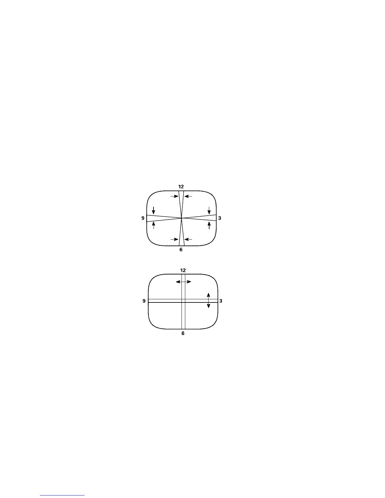
Figure 2
Dynamic Edge Convergence Adjustment
Note: To secure the correct position of the deflection yoke, three rubber wedges are used. They are ultimately to
be placed as shown in Figure 3c or Figure 4c.
1. Apply a crosshatch pattern to the antenna/cable input terminal.
2. Use the Menu Left/Right keys to select Green (G), and use the Menu Up/Down keys to set Green to
minimum.