EasyManua.ls Logo

Philips 42PFL3603D/27 User Manual

Philips 42PFL3603D/27
96 pages
To Next Page IconTo Next Page
Page #1 background imageLoading...
Page #1 background image
Published by WF 0864 BU TV Consumer Care Printed in the Netherlands Subject to modification EN 3122 785 17741
©
Copyright 2008 Koninklijke Philips Electronics N.V.
All rights reserved. No part of this publication may be reproduced, stored in a
retrieval system or transmitted, in any form or by any means, electronic,
mechanical, photocopying, or otherwise without the prior permission of Philips.
Color Television Chassis
LC8.1U
LA
H_17740_000.eps
240408
MG8
MG8
ME8
ME8
Contents Page Contents Page
1. Technical Specifications, Connections, and Chassis
Overview 2
2. Safety Instructions, Warnings, and Notes 6
3. Directions for Use 7
4. Mechanical Instructions 8
5. Service Modes, Error Codes, and Fault Finding 20
6. Block Diagrams, Test Point Overview, and
Waveforms
Wiring Diagram 32" (ME8/MG8) 33
Wiring Diagram 42" & 47" (ME8/MG8) 34
Wiring Diagram 52" (ME8/MG8) 35
Block Diagram Video 36
Block Diagram Audio 37
Block Diagram Control & Clock Signals 38
SSB: Test Points (Bottom Side) 39
I2C IC Overview 40
Supply Lines Overview 41
7. Circuit Diagrams and PWB Layouts Diagram PWB
SSB: DC / DC Converter (B1) 42 59-68
SSB: Tuner & Demodulator (B2) 43 59-68
SSB: Class-D & Muting (B3) 44 59-68
SSB: MT5382-Power & Tuner (B4A) 45 59-68
SSB: MT5382-DDR2 SDRAM (B4B) 46 59-68
SSB: MT5382-Flash & NVM (B4C) 47 59-68
SSB: MT5382-LVDS (B4D) 48 59-68
SSB: MT5382-HDMI & Mux (B4E) 49 59-68
SSB: MT5382-Analog I/Os (B4F) 50 59-68
SSB: MJC MT8280-Power (B5P) 51 59-68
SSB: MJC MT8280-DDR2 (B5Q) 52 59-68
SSB: MJC MT8280-LVDS (B5R) 53 59-68
SSB: FPGA-AmbiLight (B6K) 54 59-68
SSB: ITV-Channel Decoder (Reserved) (B7L) 55 59-68
SSB: ITV-Pro:Idiom (Reserved) (B7M) 56 59-68
SSB: SRP List Explanation 57
SSB: SRP List Part 1 58
Keyboard Control Panel (E) 69 70
Keyboard Control Panel (E) 69 71
IR & LED Panel(J) 72 73
8. Alignments 75
9. Circuit Descriptions, Abbreviation List, and IC Data
Sheets 79
Abbreviation List 89
IC Data Sheets 91
10. Spare Parts List 95
11. Revision List 95
Question and Answer IconNeed help?

Do you have a question about the Philips 42PFL3603D/27 and is the answer not in the manual?

Philips 42PFL3603D/27 Specifications

General IconGeneral
Screen Size42 inches
Display TechnologyLCD
Backlight TypeCCFL
HDMI Ports3
USB Ports1
HD typeFull HD
Aspect ratio16:9
Response time5 ms
Display brightness500 cd/m²
Viewing angle, horizontal176 °
Viewing angle, vertical176 °
Comb filter3D
Audio systemNicam Stereo
RMS rated power20 W
Component video (YPbPr/YCbCr) in1
SCART ports quantity1
S-Video inputs quantity1
PC in (D-Sub)1
HDMIYes
Refresh Rate60 Hz
Sound Output20W
Resolution1920 x 1080 pixels
Display diagonal106 cm
Dynamic contrast ratio marketing nameDynamic Contrast Ratio
Width (with stand)1042 mm
Depth (with stand)26.5 cm
Height (with stand)738 mm
Width (without stand)1042 mm
Depth (without stand)8 cm
Height (without stand)680 mm
Display resolution1920 x 1080 pixels

Summary

Technical Specifications, Connections, and Chassis Overview

1.1 Technical Specifications

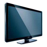
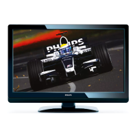
Details display type, screen size, resolution, contrast ratio, response time, and viewing angles.

1.2 Connection Overview

Lists side and rear I/O connections, including HDMI, USB, AV, S-Video, and antenna inputs.

Safety Instructions, Warnings, and Notes

2.1 Safety Instructions

General safety regulations for repair, isolation transformer use, and safety components replacement.

2.2 Warnings

ESD precautions, high voltage warnings, and advice on tool usage during service.

Mechanical Instructions

4.3 Assy/Panel Removal ME8 Styling

Steps for removing back cover, speakers, boards, and LCD panel with warnings.

Service Modes, Error Codes, and Fault Finding

5.1 Test Points

Location and use of test points, including measurement conditions and test patterns.

5.2 Service Modes

Overview of Service Modes (SDM, SAM, CSM, ComPair) and general notes on their functions.

5.4 Error Codes

Purpose of error codes, error buffer, and how to read/clear them for fault diagnosis.

5.5 The Blinking LED Procedure

How the blinking LED procedure indicates errors and displays the entire error buffer.

5.7 Software Upgrading

Instructions for upgrading TV software via USB, including file contents and NVM data transfer.

Block Diagrams, Test Point Overview, and Waveforms

Block Diagram Video

Block diagrams illustrating video signal flow and processing within the chassis.

Block Diagram Audio

Block diagrams illustrating audio signal processing and output.

Circuit Diagrams and PWB Layouts

Alignments

Circuit Descriptions, Abbreviation List, and IC Data Sheets

Related product manuals