EasyManua.ls Logo

Philips 32PFL5606H/58 User Manual

Philips 32PFL5606H/58
112 pages
To Next Page IconTo Next Page
Page #1 background imageLoading...
Page #1 background image
Published by MB/SaS/WS 1166 BU TV Consumer Care, the Netherlands Subject to modification EN 3122 785 19081
2011-Jun-10
©
Copyright 2011 Koninklijke Philips Electronics N.V.
All rights reserved. No part of this publication may be reproduced, stored in a
retrieval system or transmitted, in any form or by any means, electronic, mechanical,
photocopying, or otherwise without the prior permission of Philips.
Colour Television Chassis
TPM6.1E
LA
19080_000_110301.eps
110329
Contents Page Contents Page
1. Revision List 2
2. Technical Specs, Diversity, and Connections 2
3. Precautions, Notes, and Abbreviation List 6
4. Mechanical Instructions 10
5. Service Modes, Error Codes, and Fault Finding 17
6. Alignments 26
7. Circuit Descriptions 28
8. IC Data Sheets 39
9. Block Diagrams
Wiring diagram Thriller 32" 53
Wiring diagram Thriller 42" 54
Block Diagram Thriller 56
Block Diagram Berlinale xxPFL5606 57
Block Diagram Berlinale xxPFL5406 58
10. Circuit Diagrams and PWB Layouts Drawing PWB
A01 715G4801 PSU Thriller 32"
59
Adapter (A01) 59 61-62
Inverter (A02) 60 61-62
A01 715G4802 PSU Thriller 42" 63
Adapter (A01) 63 65-66
Inverter (A02) 64 65-66
A01 715G4738 PSU Berlinale 67
Adapter (A01) 67 69-70
LED (A02) 68 69-70
B 715G4609 SSB Thriller 71
System Power 1 (B01) 71 87-88
System Power 2 (B02) 72 87-88
Peripheral (B03) 73 87-88
Connector/USB/RS232 (B04) 74 87-88
Audio IO/Headphone (B05) 75 87-88
Speaker (B06) 76 87-88
Video IO/SPDIF (B07) 77 87-88
SCART (B08) 78 87-88
VGA Input (B09) 79 87-88
LVDS (B10) 80 87-88
DRAM Interface (B11) 81 87-88
GPIO (B12) 82 87-88
HDMI Switch/Connector (B13) 83 87-88
DVB T/C Demodulator MT5135 (B14) 84 87-88
DVB T/C Tuner (B15) 85 87-88
TCON/POWER BLOCK/GAMMA (B16) 86 87-88
B 715G4722 SSB Berlinale 88
System Power 1 (B01) 88 104-105
System Power 2 (B02) 89 104-105
Peripheral (B03) 90 104-105
Connector/USB/RS232 (B04) 91 104-105
Audio IO/SPDIF/Headphone (B05) 92 104-105
Speaker/Sound woofer (B06) 93 104-105
Video IO/YPbPr (B07) 94 104-105
SCART (B08) 95 104-105
VGA Input (B09) 96 104-105
LVDS (B10) 97 104-105
DRAM Interface (B11) 98
104-105
MII/GPIO/ServAD (B12) 99 104-105
HDMI Switch (B13) 100 104-105
DVB T/C Demodulator MT5135 (B14) 101 104-105
DVB T/C Tuner (B15) 102 104-105
TCON/POWER BLOCK/GAMMA (B16) 103 104-105
J 715G4702 IR Thriller 106
IR/LED board (J) 106 107
J 715G4958 IR Berlinale 108
IR/LED board (J) 108 109
11. Styling Sheets
Thriller 32" 110
Thriller 42" 111
Berlinale 32" 112
Question and Answer IconNeed help?

Do you have a question about the Philips 32PFL5606H/58 and is the answer not in the manual?

Philips 32PFL5606H/58 Specifications

General IconGeneral
BrandPhilips
Model32PFL5606H/58
CategoryTV
LanguageEnglish

Summary

Technical Specifications and Connections

Technical Specifications

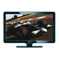
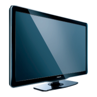
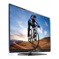
Detailed technical specifications for the TV models.

Precautions, Notes, and Abbreviation List

Safety Instructions

Essential safety regulations for performing repairs on the TV set.

Warnings

Important warnings regarding electrostatic discharge and high voltage sections.

Mechanical Instructions

Assembly/Panel Removal (Thriller styling)

Step-by-step instructions for disassembling the Thriller model.

Assembly/Panel Removal (Berlinale styling)

Step-by-step instructions for disassembling the Berlinale model.

Service Modes, Error Codes, and Fault Finding

Service Modes

Introduction to different service modes (SDM, SAM, CSM, ComPair).

Service Tools

Information on ComPair tool and necessary cables for diagnostics and software upgrades.

Software Upgrading

Procedures for updating the TV's main software via USB.

Error Codes

Explanation of error codes and the error buffer mechanism.

The Blinking LED Procedure

Using LED blinking patterns for error identification without OSD.

Fault Finding and Repair Tips

General tips for diagnosing and repairing faults, including NVM editing.

Alignments

Software Alignments

Procedures for software-based alignments, including white tone.

Reset of Repaired SSB

Procedure for resetting the NVM on a repaired SSB.

Circuit Descriptions

Power Supply

Description of the power supply unit and its management functions.

Circuit Description

Detailed descriptions of various circuits like system power, tuner, peripherals.

IC Data Sheets

Diagram Peripheral B03, MT5366CVGG BGA-479 (IC U4001)

Internal block diagram and pin configuration of the MT5366 main processor IC.

Diagram DVB T/C Demodulator MT5135 B14, MT5135AE/A LQFP-128 (IC U1005)

Block diagram and pin configuration of the MT5135 DVB T/C demodulator IC.

Diagram System Power 1 B01, TPS54319 (IC U7004)

Internal block diagram and pin configuration of the TPS54319 power supply IC.

Diagram TCON/POWER BLOCK/GAMMA B16, MAX17113ETL (IC U7008)

Block diagram and pin configuration of the MAX17113 TCON/POWER BLOCK/GAMMA IC.

Diagram TCON/POWER BLOCK/GAMMA B16, MAX9668ETP (IC U7010)

Internal block diagram and pin configuration of the MAX9668 TCON/GAMMA IC.

Diagram TCON/POWER BLOCK/GAMMA B16, TPS65192RHDR (IC U7011)

Internal block diagram and pin configuration of the TPS65192RHDR level shifter IC.

Circuit Diagrams and PWB Layouts

Related product manuals