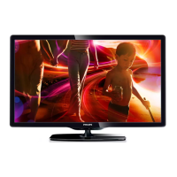
Do you have a question about the Philips 40PFL4706/F7 and is the answer not in the manual?
General safety guidelines for servicing LCD TVs, emphasizing protective devices and openings.
Technical specifications for the NTSC tuner system, including input and sensitivity ranges.
Technical specifications for the ATSC tuner system, covering frequency range and dynamic range.
Specifications for the LCD panel, detailing pixel resolution, brightness, and viewing angles.
Video specifications including over scan, color temperature, and resolution for composite video signals.
Audio specifications covering output distortion and frequency response measured across an 8-ohm load.
Pre-service return checks including protective devices, cabinet integrity, and antenna cold checks for safety.
Procedure for performing a leakage current test after reassembly to ensure electrical safety.
Warning against altering the TV's design to prevent safety hazards and warranty voidance.
Precautions regarding hot chassis configurations and necessary safety measures during servicing.
Information on safety-related parts and the importance of using specified replacements for user safety.
Specifies required clearance distances between components and metallic parts for electrical safety.
Details the method and ratings for performing a leakage current test using a specific load configuration.
Explains common markings on PCBs like pin indicators for ICs and connectors.
Guidance on identifying and using lead-free solder for specific PCBs based on markings.
Instructions for proper grounding of the technician's body using a grounding band.
Guidelines for grounding the workbench and conductive surfaces to prevent electrostatic discharge.
A flowchart illustrating the step-by-step process for disassembling the TV cabinet and accessing internal components.
Detailed steps and notes for removing and installing various cabinet parts and CBAs.
Describes a service mode for checking the purity of screen colors by displaying full-screen red, green, blue, and white patterns.
Step-by-step guide to enter the TV's hidden service menu using specific remote control button sequences.
Troubleshooting flowchart for power-on issues, guiding through voltage checks and component replacements.
Troubleshooting flowchart for key operation failures, focusing on voltage checks and circuit tracing.
Troubleshooting flowchart for remote control non-operation, guiding through voltage and signal checks.
Illustrates the main control system of the TV, showing interactions between the CPU, memory, and peripherals.
Depicts the signal flow for video and audio inputs and outputs, including tuner, HDMI, and component connections.
Shows the internal processing of digital video and audio signals, including A/D conversion, decoding, and LVDS transmission.
Outlines the structure of the power supply unit, indicating voltage regulation and distribution to various TV components.
General notes and warnings regarding the use of schematic diagrams, component replacement, and safety characteristics.
Displays the Y (luminance) signal waveform observed at connector JK3701 during color bar testing.
Shows the Pb (blue difference) signal waveform at connector JK3701 during color bar testing.
Displays the Pr (red difference) signal waveform at connector JK3701 during color bar testing.
Shows the composite video signal waveform observed at connector JK3706 during color bar testing.
Displays the audio signal waveform at connectors JK3704/JK3706 during color bar testing.
List of mechanical components for the TV, including cabinets, brackets, and fasteners, with part numbers.
List of items included in the product packaging, such as cartons and protective materials.
List of included accessories like remote control, batteries, cables, and manuals.
Identifies the part number for the power supply circuit board assembly.
Lists the main digital assemblies: Main, Function, and IR Sensor CBAs with their part numbers.
List of mechanical components specific to DS3/XA1 models, highlighting differences from DS1.
Part number for the power supply CBA unit for DS3/XA1 models.
Lists the main digital assemblies for DS3/XA1 models: Main, Function, and IR Sensor CBAs.
| Comb filter | 3D |
|---|---|
| Response time | 8 ms |
| Display diagonal | 46 \ |
| Display brightness | 400 cd/m² |
| Native aspect ratio | 16:9 |
| Supported video modes | 1080i, 1080p, 480i, 480p, 720p |
| Contrast ratio (typical) | 4000:1 |
| Screen format adjustments | 4:3, 14:9, 16:9, Auto, Zoom |
| Visible diagonal screen size | 102 cm |
| Supported graphics resolutions | 1024 x 768 (XGA), 1280 x 1024 (SXGA), 1280 x 768 (WXGA), 1360 x 768 (WXGA), 1440 x 900 (WXGA+), 1680 x 1050 (WSXGA+), 1920 x 1080 (HD 1080), 640 x 480 (VGA), 800 x 600 (SVGA) |
| Playback modes | Slideshow |
| RJ-12 ports quantity | 0 |
| Product color | - |
| Panel mounting interface | 400 x 400 mm |
| Supported TV bands | UHF, VHF |
| Analog signal format system | NTSC |
| Digital signal format system | ATSC |
| Audio system | Dolby Digital Plus, Stereo, SAP, SRS TruSurround HD |
| RMS rated power | 20 W |
| Number of speakers | 2 |
| Equalizer bands quantity | 5 |
| HDMI ports quantity | 4 |
| USB 2.0 ports quantity | 1 |
| Consumer Electronics Control (CEC) | Anynet+ |
| Wi-Fi standards | 802.11b, 802.11g, Wi-Fi 4 (802.11n) |
| Audio formats supported | MP3 |
| Image formats supported | JPG |
| Video formats supported | MPEG1, MPEG2 |
| AC input voltage | 120 V |
| AC input frequency | 60 Hz |
| Power consumption (standby) | 0.15 W |
| Power consumption (typical) | 145 W |
| Certification | DLNA |
| Package weight | 20701.95 g |
| Operating temperature (T-T) | 5 - 35 °C |
| Sustainability certificates | ENERGY STAR |
| Depth (with stand) | 230.12 mm |
|---|---|
| Height (with stand) | 638.04 mm |
| Weight (with stand) | 17400 g |
| Depth (without stand) | 41.91 mm |
| Width (without stand) | 963.93 mm |
| Height (without stand) | 594.1 mm |
| Weight (without stand) | 15100 g |



 Loading...