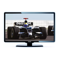
Do you have a question about the Philips 47PFL7603D/10 and is the answer not in the manual?
Provides essential safety guidelines, warnings, and notes for servicing the television.
Guides on accessing service modes, understanding error codes, and troubleshooting faults.
Provides detailed block diagrams, test point locations, and waveform information.
Presents detailed circuit diagrams and Printed Wiring Board (PWB) layouts.
Describes the procedures for performing software and hardware alignments on the TV.
Details safety regulations for repairs, including isolation transformers and component replacement.
Highlights warnings regarding electrostatic discharge (ESD), high voltage, and tool usage.
Offers practical advice on avoiding electrical shock and respecting voltages during service.
Details rules and precautions for performing lead-free soldering during repairs.
Details the procedure for removing the rear cover, including safety warnings.
Details the process of removing the LCD panel and light guide assembly.
Provides detailed instructions for removing the Small Signal Board (SSB).
Explains Service Default Mode (SDM), Service Alignment Mode (SAM), and Customer Service Mode (CSM).
Details the purpose and activation methods for SDM, used for pre-defined settings and troubleshooting.
Describes how to activate SAM using the RC transmitter or service pads.
Describes CSM for customer support, its read-only nature, and activation via RC transmitter.
Lists the available options in SAM, including Hardware Info, Operation Hours, Errors, Alignments, Dealer Options, and Store.
Details ComPair's introduction, specifications, and connection for detailed diagnostics.
Explains the error code buffer, how errors are detected, and their relation to protection.
Describes methods to read the error buffer, including SAM, blinking LED, and ComPair.
Details methods to clear the error buffer, including SAM command and RC sequence.
Provides extra information on specific error codes, their causes, and diagnostic approaches.
Explains the blinking LED procedure for protections and for displaying the error buffer.
Details methods to activate the blinking LED procedure using SDM, CSM, or specific RC commands.
Describes software and hardware protections, and various fault conditions they address.
Explains software protections related to supplies, safety checks, and system malfunctions.
Details the single hardware protection in this chassis, related to audio problems.
Provides general tips for fault finding and repair, including specific advice for Ambilight and CSM.
Guides on finding failures in DC-DC converters, including symptoms and fault finding steps.
Details troubleshooting for specific DC/DC converter issues like missing +1V2, +1V4, or unstable voltages.
Explains the possibility of upgrading main software via USB, and security key considerations.
Explains how to manually start the software upgrade application if it doesn't run automatically.
Details the software image structure and the automatic upgrade process via USB.
Describes how to perform automatic software upgrades using the AUTORUN.UPG file on a USB stick.
Explains methods for upgrading stand-by software via USB or PC/ComPair interface.
Describes the process for upgrading stand-by software using a USB stick.
Illustrates the video signal paths, including inputs, processing, and outputs.
Details the audio signal flow, including inputs, processing, amplification, and outputs.
Illustrates the control and clock signal distribution across the main components.
Provides an overview of all supply lines and their connections to various boards and ICs.
Shows the main functional blocks and signal flow for the video processing path.
Presents the block diagram detailing the audio processing path and components.
Presents the circuit diagram for the 32" display supply unit, Part 1.
Provides the circuit diagram for the LCD supply unit (37" & 42"), Part 1.
Circuit diagram for the DC/DC converters on the SSB, showing 3V3/1V2 and 12V/3V3 conversion.
Circuit diagram for the DC/DC converters on the SSB, showing 5V/1V4 and 12V/5V conversion.
Circuit diagram for the DC/DC converters on the SSB, showing 12V/1V4 and 5V/1V4 conversion.
Circuit diagram for the main tuner (TD1716) on the SSB.
Circuit diagram for the DVB-T channel decoder (TDA10048).
Circuit diagram for the DVB-C channel decoder (TDA10023).
Circuit diagram showing the control and I2C communication for the STi7101 IC.
Circuit diagram detailing the AV interface, including analog inputs and outputs.
Circuit diagram illustrating the power supply and voltage regulation for the STi7101.
Circuit diagram for the PNX8541 standby controller, detailing its pins and functions.
Circuit diagram illustrating the Non-Volatile Memory (NVM) interface for the PNX8541.
Presents the circuit diagram for the 32" display supply unit, Part 2.
Presents the circuit diagram for the LCD supply unit (37" & 42"), Part 2.
Details power supply lines, indicating incoming and outgoing signals.
Describes the main supply units for different set sizes (32", 37", 42") and their DC output protections.
Details over-voltage, short-circuit, and AC output protections for the supply units.
| Screen Size | 47 inch |
|---|---|
| Display Technology | LCD |
| Backlight Type | LED |
| Refresh Rate | 100 Hz |
| HDMI Ports | 3 |
| USB Ports | 2 |
| Audio Output | 20 W |
| Smart TV | No |
| Screen Format | 16:9 |
| Contrast Ratio (typical) | 1200:1 |
| Viewing Angle, Horizontal | 178 degrees |
| Viewing Angle, Vertical | 178 degrees |
| Comb Filter | 3D |
| Built-in Wi-Fi | No |
| 3D Capability | No |
| Resolution | 1920 x 1080 |
| Audio System | Stereo |
| Contrast Ratio | 50000:1 (dynamic) |


 Loading...