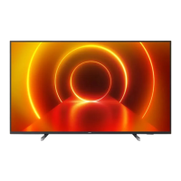
Do you have a question about the Philips 50PUS7303/12 and is the answer not in the manual?
Crucial safety regulations to follow during repair, including power connection and component replacement.
Important warnings regarding electrostatic discharge, high voltage, and handling of components during repair.
Details on purpose, specifications, activation, and navigation for SAM, used for alignments and NVM editing.
Procedures for activating and using Factory mode for extended alignments, panel ID, and test patterns.
Information on CSM purpose, specifications, and activation for customer-level diagnosis and error code retrieval.
Step-by-step guide for preparing and performing software/firmware upgrades via USB.
Explains how error codes indicate failures, how the error buffer works, and how to read it.
Details the power architecture of the platform, including display power and platform power distribution.
Circuit diagram for the 715G8886 PSU, including the input stage and PFC stage.
Circuit diagram for the 715G9106 PSU, detailing the input stage and PFC stage.
| Screen Size | 50 inches |
|---|---|
| Display Technology | LED |
| HDR Support | Yes |
| Smart TV | Yes |
| Operating System | Android TV |
| Audio Output | 20 W |
| HDMI Ports | 4 |
| USB Ports | 2 |
| Ambilight | Yes |
| Processor | Quad-Core |
| Wi-Fi | Yes |
| Bluetooth | Yes |
| Ethernet | Yes |
| Resolution | 3840 x 2160 (4K Ultra HD) |
| HDR | HLG |
| Digital TV | DVB-T/T2/C/S/S2 |
| Speaker Type | Down Firing |


 Loading...