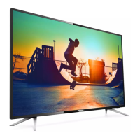
Do you have a question about the Philips 50PUT8215/56 and is the answer not in the manual?
Details screen size and resolution.
Specifies the TV's operating system.
Lists supported TV signal inputs.
Details supported video formats and refresh rates.
Lists common and TV-side/bottom ports.
Details audio output power and supported formats.
Lists wired and wireless connectivity options.
Details supported file systems for USB storage.
Lists supported media containers and codecs.
Lists supported subtitle formats and encodings.
Explains media server compatibility and usage.
Details power specifications and saving features.
Crucial safety guidelines for repair procedures.
Critical warnings for safe operation and repair.
General information and explanations for service.
Explains symbols and notations used in diagrams.
Information on sourcing replacement parts.
Guidance on handling Ball Grid Array components.
Guidelines for using lead-free soldering techniques.
Explains how to identify different Bill of Materials.
Guidance on repair strategies for boards or components.
General safety precautions for service technicians.
Reference list of technical abbreviations used in the manual.
Shows internal component layout and cable routing.
Procedures for disassembling the TV unit.
Steps to detach the TV stand.
Procedure for removing the back panel.
Procedure for removing the IR board control unit.
Procedure for removing the Small Signal Board.
Steps to remove the Power Supply Unit.
Procedure for speaker removal.
Steps to remove the Wi-Fi module.
Procedure for removing the LCD Panel.
Overview of diagnostic modes available.
Details on SAM functionality and activation.
Procedure for factory-level adjustments.
Consumer-level diagnostic information.
Instructions for updating TV firmware.
Procedure for .pkg file software updates.
Procedure for .upg file software updates.
Essential information for diagnosing failures.
Explains the purpose of error codes.
Method for accessing error logs.
Lists defined error codes.
Information on setting panel options.
Step-by-step guide for diagnosing issues.
Comprehensive guide for system-related problems.
High-level overview of system components.
Diagrams of power distribution.
Detailed power distribution analysis.
Visual guide to SSB power components.
Datasheet for the main scaler IC.
Datasheet for the audio amplifier IC.
Functional block diagram of the tuner/demodulator.
Circuit diagram for the 50" 8215 Series PSU.
AC input circuit for the 50" 8215 Series PSU.
Power Factor Correction circuit diagram.
Main power supply circuit for the TV.
Circuit diagram for the LED backlight driver.
Circuit diagram for the 55" 8215 Series PSU.
AC input circuit for the 55" 8215 Series PSU.
Power Factor Correction circuit diagram.
Main power supply circuit for the TV.
Circuit diagram for the LED backlight driver.
Circuit diagram for the 65" 8215 Series PSU.
AC input circuit for the 65" 8215 Series PSU.
Power Factor Correction circuit diagram.
LLC resonant converter circuit diagram.
Circuit diagram for the LED driver.
Circuit diagram for the 70" 8215 Series PSU.
AC input circuit for the 70" 8215 Series PSU.
Power Factor Correction circuit diagram.
LLC resonant converter circuit diagram.
LLC resonant converter circuit diagram.
Diagram showing various jumper settings.
Schematic for SOC and EMMC interface.
Schematic detailing DDR4 memory interfaces.
Schematic detailing DDR4 memory interfaces.
Schematics for DDR memory power supplies.
Schematics for the tuner and demodulator sections.
Schematic for SOC VB1 output to display.
DC-DC converter schematics for SOC power.
Schematics for system power DC-DC converters.
Schematics for system power and LNB supply.
Schematics for system power and DDR voltage regulators.
Schematic for the primary class-D audio amplifier.
Schematic for the secondary class-D audio amplifier.
Diagram of the PCMCIA interface.
Schematics for HDMI inputs and ESD protection.
Schematic for HDMI SOC interface and ARC.
Schematics for SCART, YPbPr, and CVBS interfaces.
Schematics for control connectors and interfaces.
Schematics for Ethernet, USB, and Bluetooth interfaces.
Schematics for IR board components and sensors.
Exploded view and parts list for 50"/55" models.
Exploded view and parts list for 65"/70" models.
| Screen Size | 50 inches |
|---|---|
| Display Technology | LED |
| Smart TV | Yes |
| Operating System | Android TV |
| Ambilight | Yes |
| HDMI Ports | 3 |
| USB Ports | 2 |
| Refresh Rate | 60 Hz |
| Wi-Fi | Yes |
| Ethernet | Yes |
| Bluetooth | Yes |
| Sound Output | 20 W |
| Weight | 13.5 kg |
| Resolution | 4K Ultra HD (3840 x 2160) |
| HDR Support | HDR10, HLG |


 Loading...