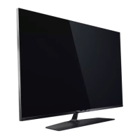
Do you have a question about the Philips 55PUS6754/12 and is the answer not in the manual?
Essential safety guidelines for performing repairs and handling the set.
Critical warnings regarding ESD, high voltage, and tool usage during repairs.
Rules and precautions for working with lead-free soldering technology.
Guidance on deciding whether to replace or repair boards.
General safety precautions for avoiding electrical shock and equipment damage.
Step-by-step guide for removing and assembling internal components like IR board and panel.
Instructions for removing the rear cover, including screw and connector locations.
Steps for safely removing the SSB, emphasizing screw and connector handling.
Guidelines for safely disconnecting and removing the PSU.
Detailed steps for safely removing the LCD panel.
Details purpose, specifications, activation, and navigation for SAM.
Explains the purpose, specifications, and activation of the Factory mode.
Describes CSM purpose, specifications, activation, and navigation for customer support.
Instructions for updating TV software using USB for .pkg and .upg files.
Explains the purpose and structure of error codes and the error buffer.
Details the procedure for setting option codes via RC transmitter and provides a table of codes.
Flowchart guiding through systematic troubleshooting of system-related and intermittent issues.
Overview of the platform's power architecture, detailing display and platform power.
Schematic for the AC input section of the 715GA018 PSU.
Schematic for the Power Factor Correction circuit using LD7592S.
Schematic for the LED driver circuit using PF7904.
Schematic for the AC input of the 715GA052 PSU.
Schematic for the Power Factor Correction circuit using LD7592GS.
Schematic detailing the main power supply stages including LLC and regulators.
Schematic for the LED driver circuit using PF7909S.
Schematic for the AC input of the 715GA025 PSU.
Schematic for the Power Factor Correction circuit using LD7592.
Schematic for the LLC resonant converter circuit using SSC3S927.
Schematic of the SSB including power management and CPU/GPU power rails.
| Screen Size | 55 inches |
|---|---|
| Display diagonal | 139 cm |
| Resolution | 4K Ultra HD |
| Display resolution | 3840 x 2160 pixels |
| Display Technology | LED |
| Screen shape | Flat |
| Smart TV | Yes |
| Internet TV | Yes |
| Native aspect ratio | 16:9 |
| Number of speakers | 2 |
| RMS rated power | 20 W |
| Audio Power | 20 W |
| Sound Output | 20W |
| Wi-Fi | Yes |
| Ethernet LAN | Yes |
| Bluetooth | Yes |
| VESA mounting | Yes |
| VESA mounting interfaces | 200 x 200 mm |
| Product colour | Black |
| HDMI ports quantity | 3 |
| USB 2.0 ports quantity | 2 |
| HDR | Yes |
| Processor | Quad-core |
| Weight | 15.5 kg |
| Motion interpolation technology | Perfect Motion Rate |
| Digital signal format system | DVB-T, DVB-T2, DVB-C, DVB-S, DVB-S2 |


 Loading...