Do you have a question about the Philips 55PUS6262/12 and is the answer not in the manual?
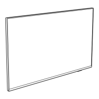
Procedures for disassembling and removing TV components.
Detailed steps for removing the LCD panel.
Mode for alignment, NVM modification, and error buffer management.
Mode for extended alignments and software settings.
Mode for displaying error codes and diagnostic information.
Purpose, specifications, activation, and navigation for SAM.
Purpose, specifications, and activation for Factory Mode.
Purpose, specifications, and activation for CSM.
Procedures for updating TV software.
Steps for updating software using a .pkg file.
Steps for updating software using a .upg file.
Information on error codes and their meaning.
Explanation of error code system and error buffer.
Methods to read error codes from the buffer.
Table detailing specific error codes and their causes.
Procedures to clear stored error codes.
Instructions for setting the panel code.
Details on the power supply system.
Information on the PSU's architecture and control signals.
Voltages provided by onboard DC/DC converters.
Key components for analogue and digital TV reception.
Details on HDMI connectors and their functions.
Features and capabilities of the main MT5802VGEJ processor.
Block diagram and pinout for the MT5802VGEJ IC.
Pinout and block diagram for the AD82588B audio amplifier IC.
Pinout for the TLC5971RGER LED driver IC.
Schematic for the Power Supply Unit (PSU) for 43" models.
| Screen Size | 55 inches |
|---|---|
| Display Technology | LED |
| Smart TV | Yes |
| HDR | Yes |
| Ambilight | Yes |
| HDMI Ports | 3 |
| USB Ports | 2 |
| Screen Shape | Flat |
| Aspect Ratio | 16:9 |
| Internet TV | Yes |
| Operating System | SAPHI |
| Refresh Rate | 60 Hz |
| Wi-Fi | Yes |
| Bluetooth | No |
| Sound Output | 20 W |
| Component Video (YPbPr/YCbCr) In | 1 |
| Digital Audio Optical Out | 1 |
| Headphone Outputs | 1 |
| Common Interface (CI) | Yes |
| Common Interface Plus (CI+) | Yes |
| VESA Mounting | Yes |
| VESA Mounting Interfaces | 200 x 200 mm |
| Product Colour | Silver |
| Resolution | 3840 x 2160 pixels |
| Motion Interpolation Technology | PMR (Perfect Motion Rate) |
| HDR Formats | HDR10 |
| HDMI Version | HDMI 2.0a |