Do you have a question about the Philips 55PUS7303/12 and is the answer not in the manual?
Safety regulations for repair.
Important warnings and precautions during repair.
Steps to remove the small signal board (SSB) from the TV.
Procedure for removing the power supply unit (PSU).
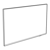
Steps for removing the LCD panel from the TV bezel.
Overview of different service modes like SAM, Factory, and CSM.
Purpose and specifications of SAM mode for alignments and information display.
Purpose and specifications for performing extended alignments and test patterns.
Purpose and specifications of CSM mode for diagnosis and error reporting.
Steps for preparing and performing software upgrades via USB.
Introduction to error codes and how they indicate TV failures.
Procedure to set the panel code using the remote control.
Power architecture of the platform showing display and platform power distribution.
Detailed breakdown of power distribution from main 12V to various components.
Schematic for the first-class-D audio amplifier.
Schematic for the second-class-D audio amplifier.
Schematics for the HDMI input ports.
Schematic for HDMI SOC and Audio Return Channel.
Schematic for SCART, YPbPr, and CVBS inputs.
Schematic for the Ethernet PHY and Wi-Fi control.
Schematic for the first-class-D audio amplifier.
Schematic for the second-class-D audio amplifier.
Schematics for the HDMI input ports.
Schematic for HDMI SOC and Audio Return Channel.
Schematic for SCART, YPbPr, and CVBS inputs.
Schematic for the Ethernet PHY and Wi-Fi control.
| Screen Size | 55 inches |
|---|---|
| Display diagonal | 139 cm |
| Resolution | 3840 x 2160 pixels |
| Display Technology | LED |
| Screen shape | Flat |
| Smart TV | Yes |
| Operating System | Android |
| Operating system installed | Android TV |
| Internet TV | Yes |
| HDR Support | Yes |
| Motion interpolation technology | Perfect Natural Motion |
| Native aspect ratio | 16:9 |
| Wi-Fi | Yes |
| Ethernet LAN | Yes |
| Bluetooth | Yes |
| VESA mounting | Yes |
| Ambilight | Yes |
| HDMI Ports | 4 |
| USB Ports | 2 |
| Processor | Quad Core |
| Built-in Speakers | Yes |
| Audio Output | 20 W |
| Digital signal format system | DVB-T, DVB-T2, DVB-C, DVB-S, DVB-S2 |