2003 Sep 19 19
Philips Semiconductors Product Specification
VHF push-pull power MOS transistor BLF278
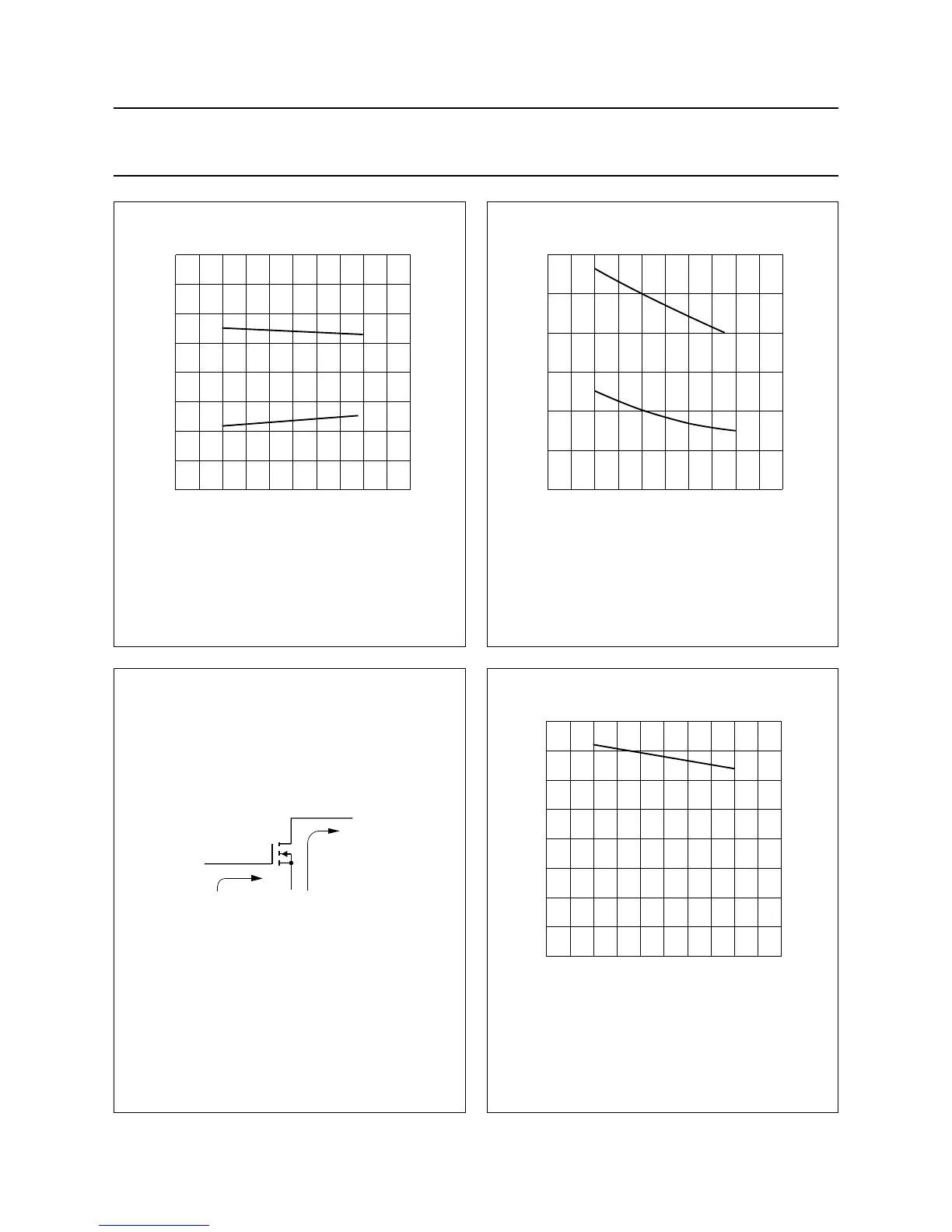
Fig.23 Input impedance as a function of frequency
(series components); typical values per
section.
Class-AB operation; V
DS
= 50 V; I
DQ
=2×0.5 A;
R
GS
= 2.8 Ω (per section); P
L
= 250 W.
handbook, halfpage
150 200 250
2
1
−1
–2
0
MGE611
r
i
z
i
(Ω)
x
i
f (MHz)
Fig.24 Load impedance as a function of frequency
(series components); typical values per
section.
Class-AB operation; V
DS
= 50 V; I
DQ
=2×0.5 A;
R
GS
= 2.8 Ω (per section); P
L
= 250 W.
handbook, halfpage
150 250200
f (MHz)
3
2
1
0
MGE625
X
L
R
L
Z
L
(Ω)
Fig.25 Definition of MOS impedance.
handbook, halfpage
MBA379
Z
i
Z
L
Fig.26 Power gain as a function of frequency;
typical values per section.
Class-AB operation; V
DS
= 50 V; I
DQ
=2×0.5 A;
R
GS
= 2.8 Ω (per section); P
L
= 250 W.
handbook, halfpage
150 200 250
20
0
10
MGE624
G
p
(dB)
f (MHz)