2003 Sep 19 3
Philips Semiconductors Product Specification
VHF push-pull power MOS transistor BLF278
LIMITING VALUES
In accordance with the Absolute Maximum System (IEC 60134).
THERMAL CHARACTERISTICS
SYMBOL PARAMETER CONDITIONS MIN. MAX. UNIT
Per transistor section
V
DS
drain-source voltage − 125 V
V
GS
gate-source voltage −±20 V
I
D
drain current (DC) − 18 A
P
tot
total power dissipation T
mb
≤ 25 °C; total device; both
sections equally loaded
− 500 W
T
stg
storage temperature −65 150 °C
T
j
junction temperature − 200 °C
SYMBOL PARAMETER CONDITIONS VALUE UNIT
R
th j-mb
thermal resistance from junction
to mounting base
total device; both sections
equally loaded.
max. 0.35 K/W
R
th mb-h
thermal resistance from
mounting base to heatsink
total device; both sections
equally loaded.
max. 0.15 K/W
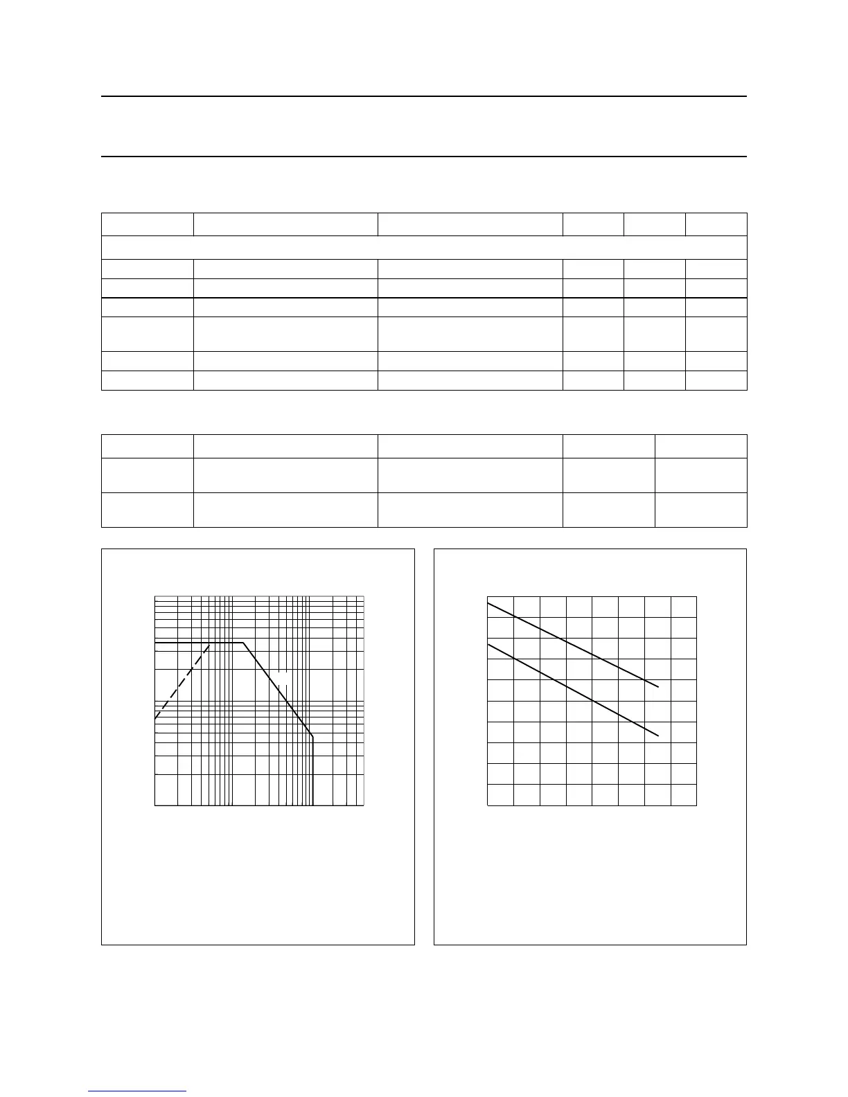
Fig.2 DC SOAR.
Total device; both sections equally loaded.
(1) Current is this area may be limited by R
DSon
.
(2) T
mb
=25°C.
handbook, halfpage
1
10
100
1 10 100
(1)
500
I
D
(A)
V (V)
DS
MRA988
(2)
Fig.3 Power derating curves.
Total device; both sections equally loaded.
(1) Continuous operation.
(2) Short-time operation during mismatch.
handbook, halfpage
0 40 80 160
500
0
400
MGE616
120
300
200
100
P
tot
(W)
T
h
(°C)
(2)
(1)
 Loading...