Repair procedure
Since the light pen is very sensitive to static charges, the
tools and yourself must have the same potential as the
CD mechanism when measuring and adjusting the laser
power supply.
• Remove the flex board from connector A11 and connect the
simulator board to the connector.
• Remove plug A16 and insert it into the connector on the
simulator board. Connect the 4-wire plug to connector A16.
• Disconnect plug A17 and insert the 4-wire plug into
connector A17.
• Bypass the lid switch.
• Switch on the power switch, press the play button and check
whether the L-line of the servo µP goes "low".
• In the quiescent state, current through the laser diode
should be ≤ 1 mA. This can be checked as follows:
• Set the switch on the simulator board to the "OFF" position
and the power switch to the “ON” position.
• Turn bias resistor 3180 counterclockwise (min.R) and
measure voltage across resistor 3194.
• For NEG. VOLT the voltage must be ≤10mV.
• For POS. VOLT the voltage must be ≤15mV.
Checking the control of the laser power supply:
NEG.VOLT:
Set the switch on the simulator board to the "ON" position
and measure the voltage between point V and ground on the
simulator board.
Resistance 3180 clockwise (max. R):
Uv to ground = -120mV ± 24 mV.
Resistance 3180 counterclockwise (min. R):
Uv to ground = -720mV ± 144 mV.
Set resistor 3180 so that Uv to ground = ≈ -500 mV.
This is a preset. After the simulator board has been removed,
the laser current must be set.
POS.VOLT:
Set the switch on the simulator board in the "ON" position and
measure the voltages between the +V and -V points on the
simulator board.
Resistance 3180 clockwise (max. R):
U+v to v = 60mV ± 30 mV
Resistance 3180 counterclockwise (min. R):
U+v to v = 560mV ± 50 mV.
Put resistor 3180 in the centre/mid position.
This is a preset. After the simulator board has been removed,
the laser current must be set.
Fine adjustment of the laser current:
Play track 1 of test disc 4322 397 30086 (CD without defects).
Connect a DC voltmeter across resistor 3308 on the servo
board, principal diagram D.
Regulate the laser power supply with resistor 3180 so that the
voltage across resistor 3308 is 500 mV ± 50 mV.
Attention:
A laser current that is too high (> 500 mV across resistor
3308) shortens the life of the laser diode.
Note:
It is recommended to use the laser simulator board for every
measurement in the laser power supply, because short-term
closures with the measuring probe can have nasty
consequences for the laser diode
Annex II: PLL CIRCUIT CAPTURE CHECK
(Measuring points on the decoder board, principal scheme F)
First of all, the free-running oscillator should be checked and
adjusted as follows:
• Put the device in stop position.
• Connect a frequency counter between point 22 of IC 6501
(DEMOD) and ground.
• Use coil 5501 to adjust the frequency to 4.350MHz ±5KHz.
Attention
This setting must be made immediately after switching on
the device.
Capture control.
• Place a CD on the turntable.
• Disconnect plug A14, inject a DC voltage of 2.5V on the
connector of plug A14 (on the preamplifier, principal diagram
E), and bring the device into service loop B.
• Varying the DC voltage around 2.5V should be visible on the
oscilloscope at measuring point <71> in the form of
frequency variation. This means that the PLL then locks.
Annex III: CONTROL OF THE d-FACTOR
(Measuring points on the servo print, principal diagram D)
Connect test point <20> to ground.
(If a fixed resistor is mounted instead of potentiometer 3315, a
resistor of 330KΩ must be placed between the measuring
points <32> and <33>).
Place a CD on the turntable and bring the unit into service
loop A
• Check the measuring points <23> and <22>.
Their value should be 0.7 Vpp.
The frequency variation is strongly dependent on the
eccentricity of the CD.
• Check measurement point <25>.
The value should be 250mVpp.
• Check measurement point <35>.
The value should be 200mVpp.
• Check measurement point <36>.
The value should be 2Vpp.
• Check measuring points <37> and <38>.
Their value should be 10Vpp.
The signal is now more sinusoidal due to the 650Hz lift.
• Measuring point <39> is difficult to measure because the
switch is in position Yoc and is therefore connected to the
input of Op-Amp 6215.
However, a signal of 200mVpp is present.
• Check measuring point <40>.
The value should be 9 Vpp.
Bring the device into service loop B. A CD will still be located
on the turntable and measuring point <20> will still be
connected to ground (and, if necessary, the 330KΩ resistor is
still connected between measuring points <32> and <33>).
Check measuring point <41>.
Check measuring point <40> on beam A of the oscilloscope
and measuring point <39> on beam B of the oscilloscope.
Trigger the oscilloscope with measuring point <41>.
Disconnect measuring point <20> from ground, place the
device in service loop A and check whether measuring point
<20> can be set to zero volts using 3315. (If, instead of 3315,
a fixed resistor is mounted, disconnect test point <20> from
ground, remove the 330KΩ resistor between test points <32>
and <33>. Bring the device into service loop A and check
whether the voltage at Measuring point <20> is between -5V
and +5V).
Annex IV: CHECKING THE k-FACTOR
(Measuring points on the servo print, principal diagram D)
a. Static
Only turn on the power switch.
i.e. RCO = high; (NOT)RCO = low so switch Yb is in position 0
and switch Yc is in position D.
• Check measuring point <45>.
The value should be 9Vpp.
• Check measuring point <46>.
• At measuring point <29> there is now a sinusoidal signal of
650Hz, 300 mV and 180°- 45° = 135° phase shifted with the
signal at measuring point <45>.
• Check measuring point <47>.
The value should be 1.5Vpp.
• Check measuring point <48>.
The value should be 1Vpp.
• Check the measuring points <49>, <50>, <51> and <46> in
relation to each other.
The amplitudes are 5V.
• Check integrator IC6212A.
b. Dynamic
• Place a CD on the turntable. Bring the device into service
loop A and check whether the signal at measuring point
<21> is 7Vpp.
• Bring the device into service loop B.
Now (NOT)RCO = high and RCO = low.
So switch Yb is in position 1 and switch Yc switches with a
frequency of 650Hz.
Measuring point <52> is low, so measuring point <51> is in
phase with measuring point <50>.
Now at measuring point <51> Fig. U must be present with a
jittered duty cycle of around 50%
Annex V: CHECKING THE HF PRE-AMPLIFIER
(Principal scheme E)
a. Check DC voltages across transistors 6103, 6104, 6105,
6109, 6110 & 6111.
b. Sensitivity control. frequency and delay characteristic:
• Take the flex boards out of the connectors A10 and A11.
• Remove the plugs A12 A13, A14, A15, A17 and A18.
• Note: DO NOT disconnect plug A16 (= power supply).
• Unscrew the PCB to inject on the track side.
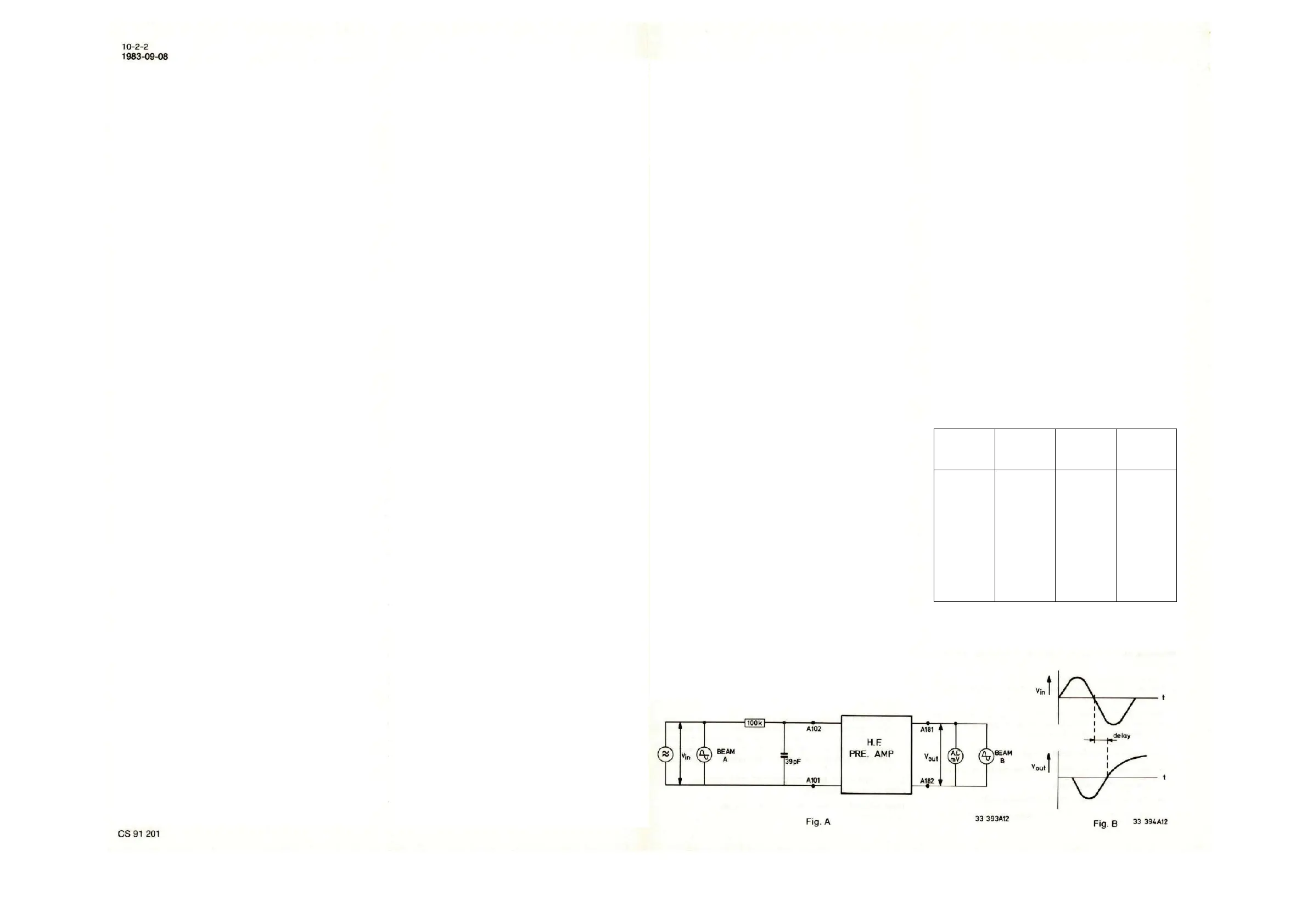
Sensitivity
• Inject according to the scheme below (fig. A) between the
points A101 and A102 a signal V
in
of 140mV
eff
, 50kHz, via
RC network (see fig. A).
• The output voltage between the points A181 and A182
should be 245mV ±2dB.
Note: Make sure that the injection lead and the test lead are
identical.
Frequency and delay characteristic:
• Set V
in
so that V
out
= 245mV = 0dB at 50kHz. See Fig. A.
• The re-delay between the injected signal and the
measured signal must be 450nsec ±50nsec at 300kHz.
This can be measured using a double-beam oscilloscope,
with V
in
on beam A and V
out
on beam B. (see Fig. B).
• Check the frequency and delay characteristics for the
frequencies given below.
Delay,
compared
to the delay
at 300kHz
1
6.3
16
50
100
200
300
500
700
1000
1600
2000
-15 ±3
-2 ±3
-0.5 ±3
0 ±3
0 ±1
+1 ±1
+1.5 ±1
+3.5 ±1
+5.5 ±2
+8 ±2
+8 ±2
+4.5 ±3
-50 ±20
0 ±20
0
+20 ±20
+30 ±20
+30 ±20
 Loading...