Do you have a question about the Philips CD604 and is the answer not in the manual?
Safety requirements for restoring original condition and using identical parts.
Warning statement for laser product safety compliance.
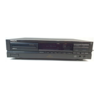
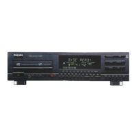
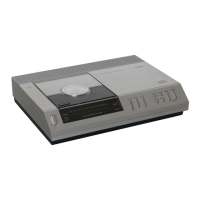
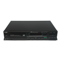
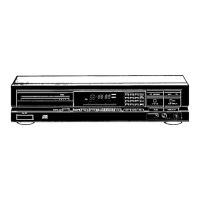
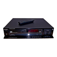
Identification and function of player's front panel buttons and indicators.
Details of audio/digital outputs, mains inlet, and remote control connections.
Mains voltage, frequency, power, RC-5 input, and line output specifications.
Fixed/variable headphone output power and laser diode wavelength/power.
Overall apparatus dimensions and total weight.
Hints on chip components, disc hold-down, and electrical safety during servicing.
List of specialized tools and discs required for service.
Techniques for component removal, mounting, and safety during repair.
Procedures for using a service disc hold-down and foil for CDM.
Warnings and procedures for handling sensitive electronic components safely.
Illustrated steps for removing the player's cabinet housing.
Steps for disassembling the disc loading mechanism and CDM unit.
Instructions for fitting an insulation cover for electrical safety.
Visual representation of the player's internal components and their assembly.
List of mechanical parts with corresponding part numbers for identification.
Step-by-step guide to diagnose and resolve operational faults using flowcharts.
Procedures for checking laser supply and adjusting laser current and focus offset.
Comprehensive table detailing system error codes and their meanings.
Flowchart illustrating the correct sequence for powering on and initializing the player.
Schematic diagram detailing the power supply unit and its components.
Schematic and component list for the variable headphone output stage.
High-level block diagram illustrating the functional relationships within the CD mechanism.
Definitions and explanations for various signal names used throughout the manual.
Detailed schematic outlining the servo control circuits for disc operation.
Continuation of servo schematic with associated component references.
Diagram showing component placement and connections on the main circuit board's solderside.
Diagram illustrating component placement on the main circuit board's component side.
Schematic and component list for the audio and digital signal decoding circuits.
Explanations of signals processed within the decoder circuit.
Schematic and component list for the front panel display unit.
Diagram of RAM usage and parts list specific to the display interface.
Layout diagram and parts list for the control and display interface board.
Diagram showing how different circuit boards are connected within the player.
Detailed list of components for the servo and decoder circuit boards.
Comprehensive list of components found on the main circuit board.
List of general parts, tools, and accessories used in servicing.