Do you have a question about the Philips CD610 and is the answer not in the manual?
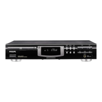
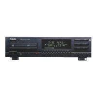
Details on the function of each player control button, including playback, search, and programming.
Information on connecting the mains lead, audio output to amplifier, and remote control system.
Detailed electrical and performance specifications for the CD player, including voltage, output levels, and frequency response.
Instructions for disassembly, chip component handling, soldering techniques, and essential safety measures like ESD protection.
List of specialized tools required for effective and safe servicing of the CD player.
Step-by-step guide for safely removing the player's cabinet for internal access.
Illustrations showing specific player orientations for testing and repair operations.
Visual diagram of the CD player's internal layout, with numbered components for reference.
List of all mechanical components with their part numbers for identification and replacement.
A systematic flowchart to identify and resolve common faults and errors within the CD player.
Procedures for checking laser performance, power supply, and adjusting focus for optimal disc reading.
Detailed explanations of system and operating error codes, helping to diagnose malfunctions.
Information on power supply configurations for different regions and details on thermal fuses.
Schematic diagrams illustrating the circuitry for the laser assembly, turntable motor, and radial motor.
Diagram showing the physical layout and component positions on the main printed circuit board.
A high-level overview of the player's internal functional blocks and their interconnections.
Descriptions of key circuits and a glossary of technical terms used in the manual.
Detailed circuit diagrams for the servo control system, including motor drivers and error processing.
Detailed circuit diagrams for the digital decoder, DAC, and filter stages.
In-depth schematic of the servo and decoder circuitry, including RAM and digital processing units.
Schematics for the Filter-B stage, digital output encoder, and digital-to-analog converter circuits.
Diagram showing the connections and components for the front panel Fluorescent Tube Display (FTD).
Schematic for the circuit board responsible for handling remote control signals and front panel display functions.
Detailed list of electrical components with part numbers, values, and specifications for replacement.
Further listings of electrical components, service tools, and accessories for comprehensive maintenance.
| Type | CD Player |
|---|---|
| Dynamic Range | 96 dB |
| Total Harmonic Distortion | 0.003% |
| Channel Separation | 90dB |
| Channels | 2 (Stereo) |
| Output Voltage | 2V |
| Digital Output | Coaxial |
| Power Consumption | 15W |
| Weight | 4.5 kg |
| Transport | CDM-4/19 |
| Frequency Response | 20 Hz - 20 kHz |
| Line Output | 2V |