The Y/UV In signal is routed directly to the
Digital Board; there is no Y/UV IN to Y/UV Out
loop through in Standby. Refer to Figure 51. The
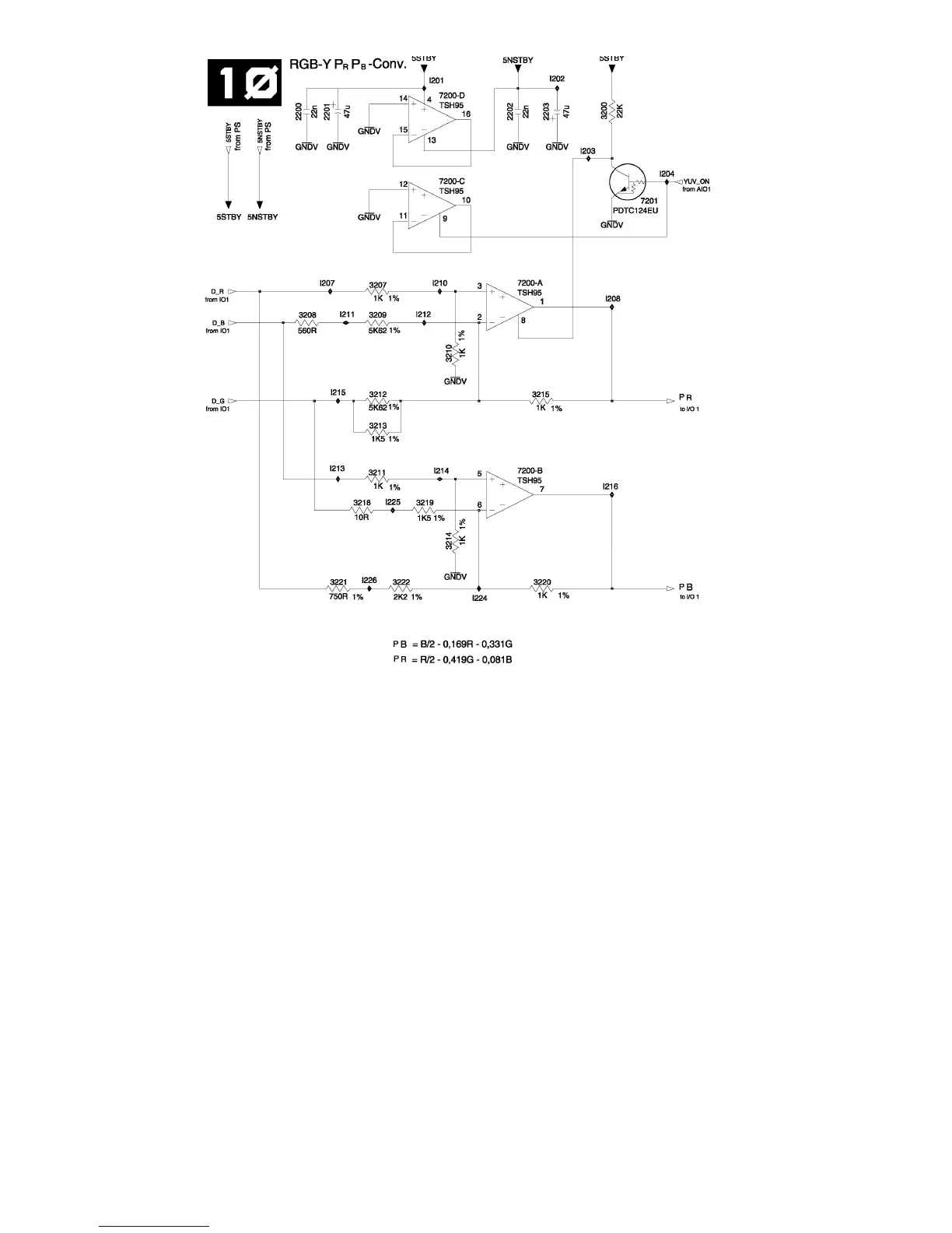
Digital Board supplies only RGB signals, a RGB
Y/UV matrix is used. This matrix consists of the
operational amplifier 7200 which generates the U
and V signals according the formulas: 2U = B -
.338R - .661G and 2V = R - .838G - .161B. Then
the signals are routed to the UV Output sockets
via the 75-Ohm driver 7516. The corresponding
Y signal is coming from the Digital Board via the
7507. The 75 Ohm Y jack is driven by 7516 con-
nected to the Y/UV Output.
Audio Conversion
Audio is converted from analog to digital for
recording purposes, and digital audio is convert-
ed to Analog during playback.
A/D
This is accomplished by 7004, Refer to Figure
52. IC7004 uses a PCM CLK signal, a Bit CLK,
and a Word CLK. An input amplitude of up to
2Vrms is expected on Pins 1 and 3. 7004 sends
the data in I
2
S format to the Digital Board via Pin
13.
D/A
After a delay, the processed audio data comes
back from the Digital Board to a D/A converter,
7001 on Pins 10, 11, and 12. 7001 converts the
I
2
S data back into a balanced analog signal on
Pins 28, 29, 31 and 32. IC 7001 uses a D_PCM
CLK signal, a D_Bit CLK, and a D_Word CLK.
Balanced to Standard Signal Conversion
7002 converts the signals from a balanced out-
put into standard cold ground referenced signals.
The signals go to 7507 on Pins 47 and 49, and
the Audio Out Jacks.
Figure 51 - RGB-Y/UV Conversion
87