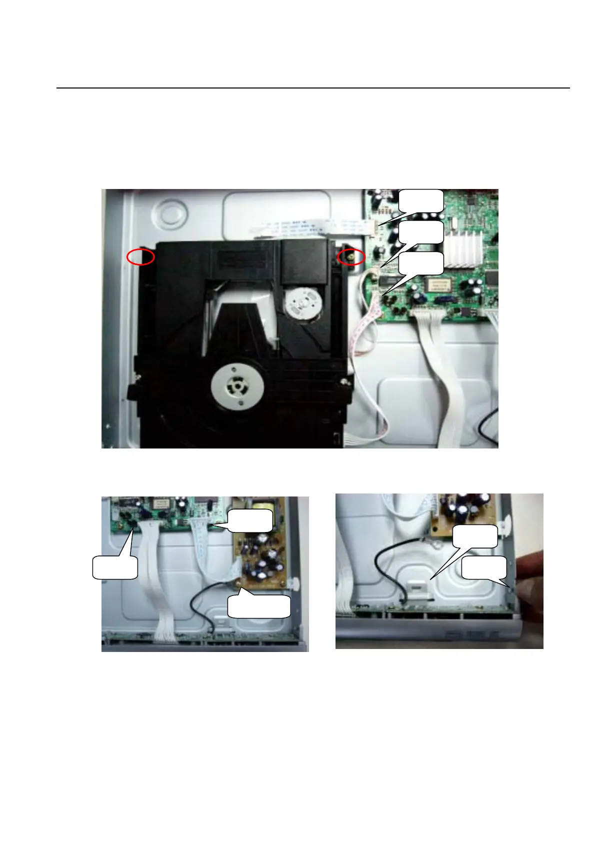
M echanical and Dism antling Instructions
Step3: Dism antling Loader, First, disconnect the 3 connectors
aiming in the figure, and then rem ove the 2 screw s at both
sides of the loader, (Figure 4)
Step4:D ism antling Front Panel: disconnect the 2 connectors
aiming in the figure then Release the snaps on the both sides
of Front P anel and gently pull the P anel out from the set.
Figure4
Figure 5Figure 6
Snap1
Snap2
CON 1
CON 2
CON 3
CON 4
CON 5
2-2
(Figure5& 6)
GND cable
www.freeservicemanuals.info