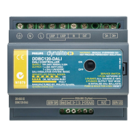
DDBC120-DALI
To reduce the risk of re or electric shock, do not expose this device to rain or moisture. Installation, programming and maintenance must be
carried out by qualied personnel. All local wiring and electrical regulations must be followed when installing device.
Overview
• Single-phase supply – 100 - 240 VAC 50 / 60 Hz at 0.25 A
• 1 x DALI Output – Suitable for DALI HF ballasts, electronic
low-voltage transformers and LED xtures. Philips Dynalite multi
master enabled for use with DPMI940-DALI and DUS360CR-
DALI only.
• 1 x Feed-through Switched Circuit – Rated at 20 A
• Built-in DALI Bus Power Supply of 220 mA @ 16 VDC –
Auto restart on overload or short circuit on DALI output. No
external DALI power supply allowed.
• Override and Status Indicator for Switched Channel
• Many Control Options – Control of this device can be via
a combination of methods, such as serial control port, relay
contacts, push button control panels, infrared receivers,
timeclocks and Philips Dynalite user interfaces on the DALI
network.
• Dry Contact Interface – Can be programmed to perform many
different functions. The factory settings will cause this input to
transmit network identication information.
• Simple Installation – DIN rail mount facilitates installation. All
connection terminals accessible without disassembly.
DALI Multi Master Controller
Warning – Read the instructions - We recommend that you read
this instruction manual prior to commencement of installation.
Standards - The temperature limits and carrying capacity of
communication wires must comply with HD 384.5.523 and the
installation of home and building automation and control systems
must comply with HD 60364-4-41.
Special Programming – This device is designed for professional
installation only, and will only operate in basic modes unless
programmed via a computer. If programming is required, contact
your local agent for details. Once the data cable is connected to
the devices, the factory default settings will allow any control panel
to control all channels in all dimmers.
Check Connections – Re-tighten all connections after installation.
Power Sources – This device should only be operated from the
type of supply specied on the front cover. This device must be
earthed.
Output Circuit – The load on the switched circuits should not
exceed the specied capacity of 20 A, these circuits should be fed
via a 20A circuit breaker.
Load Control Circuit – A 2 core DALI bus cable is required to be
run to the loads. This cable is in addition to the mains feed.
Load Type – This product is intended to control DALI drivers and
devices.
Location – Install in a dry, well-ventilated location. Controllers may
emit some mechanical noise. Take this into account when deciding
the mounting location.
Data Cable – Use screened, stranded RS485 data cable with three
twisted pairs. Segregate from mains cable by 300mm minimum.
Connect devices in a ‘daisy chain’. A data cable connected to an
energized device is live. Do not cut or terminate live data cables.
Electrical Diagram
Supply: