5. NAME OF PARTS
6. APPERANCE AND STRUCTURE
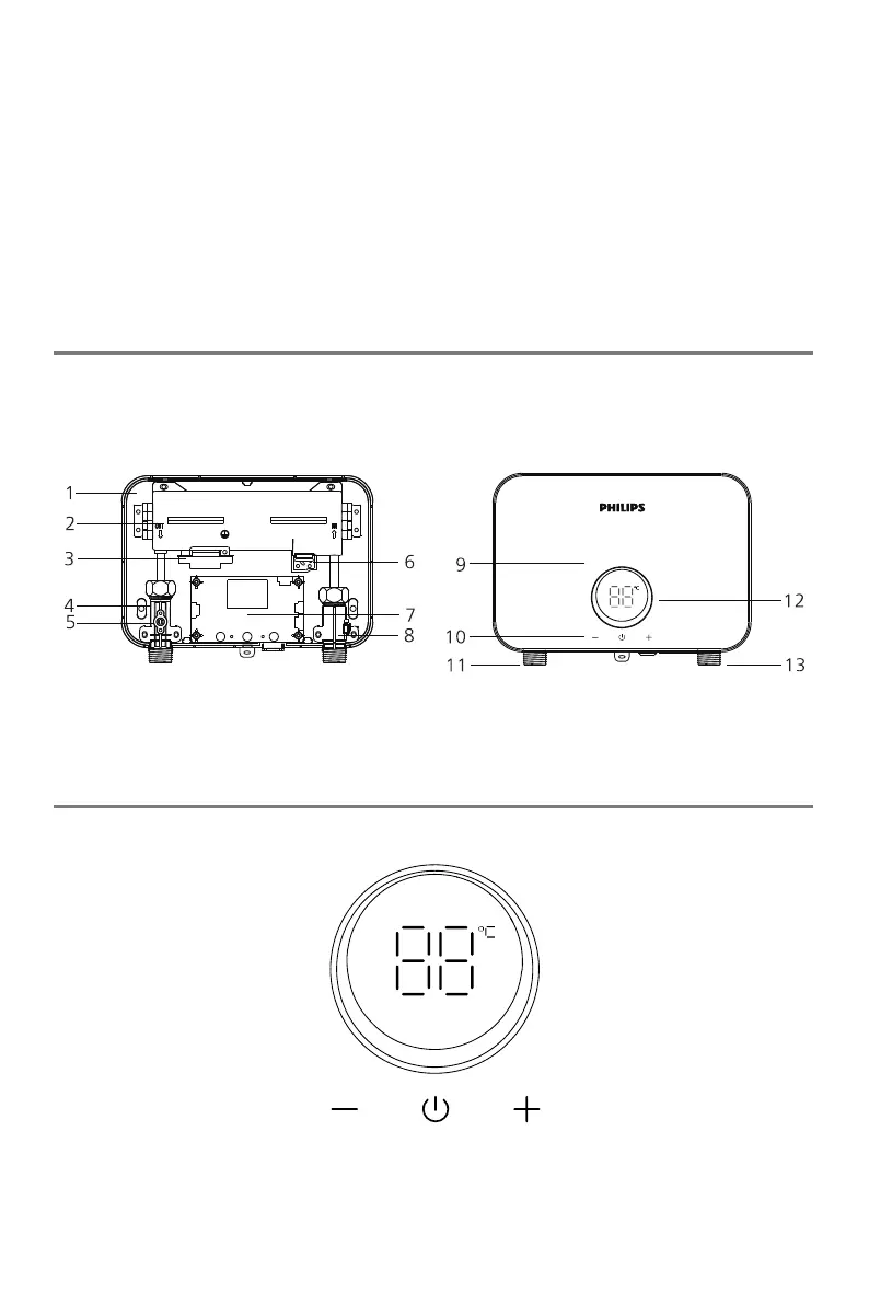
Parts of the appliance are as below:
NOTE: The picture is a schematic diagram and is subject to physical product.
The operation panel is as below:
Figure B
1. Back shell 2. Heater 3. Dry heating protector
4. Water outlet anti-electricity wall 5. Temperature sensor 6. Silicon control
7. Electric control display board 8. Flow Sensor 9. Front shell
11. Water outlet 12. Display Screen
13. Water inlet
EN 4