EPIQ 5 & 7 Training Manual
© 2016 Conquest Imaging
Time Gain Control Amp (TGC) – A variable gain amplifier (VGA) is
used to compensate for image variations due to tissue depth.
Analog to Digital converter and noise filtering.
Digital Beamformers – Upconverts signals which increases
sample rates. The signals are stored in memory, apodized and
summed.
Beamformed Digital Signal Processing – The digital beamformed
signals received are processed into visual and audio outputs the
process of which depends on if the transducer is B-mode (2D),
Doppler, PWD or CWD.
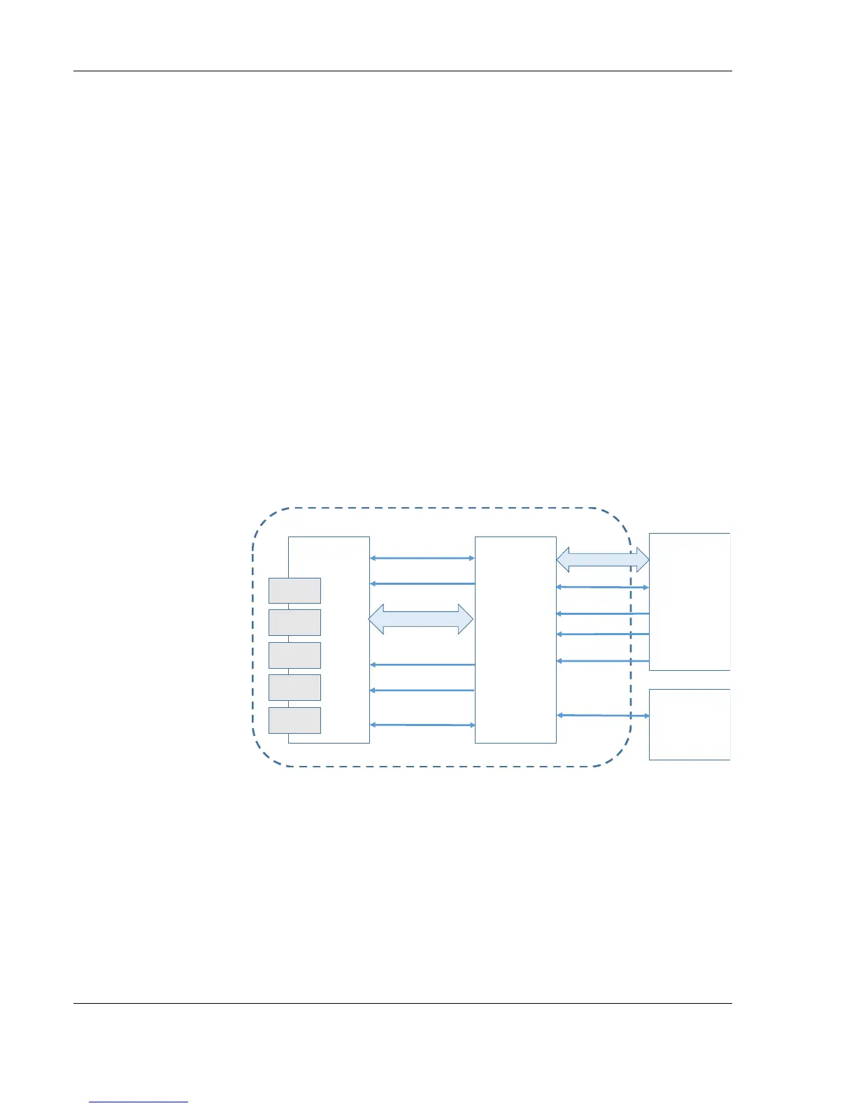
The three major boards in the Philips EPIQ system’s front end are the
Acquisition Control Board (ACB), along with the Channel Board (CB)
and the Transducer Select Board (TSB).
Front End Block Diagram
The front end manages the input from the transducers, performs
Analog to Digital conversion, Digital to Analog conversion along with
many other signal processing functions.
Acquisition Control Board ACB
The ACB contains two Field Programmable Gate Arrays (FPGA); Xenon
and Argon, that process the signal data from the digital beam-former.
ChannelBoard
Acquisition
ControlBoard
Power
Regulator
Module
Transducer
SelectBoard
FrontEndSub-system
CW
Probe
XDCR
Module
XDCR
Module
XDCR
Module
XDCR
Module
128Channel
I
2
C
MGT
Control
M atrixO S
MUX
MotorandControlCable
I
2
C
FPGAConfig
ScanDMA
C lock160MHz
PowerControl