EPIQ 5 & 7 Training Manual
© 2016 Conquest Imaging
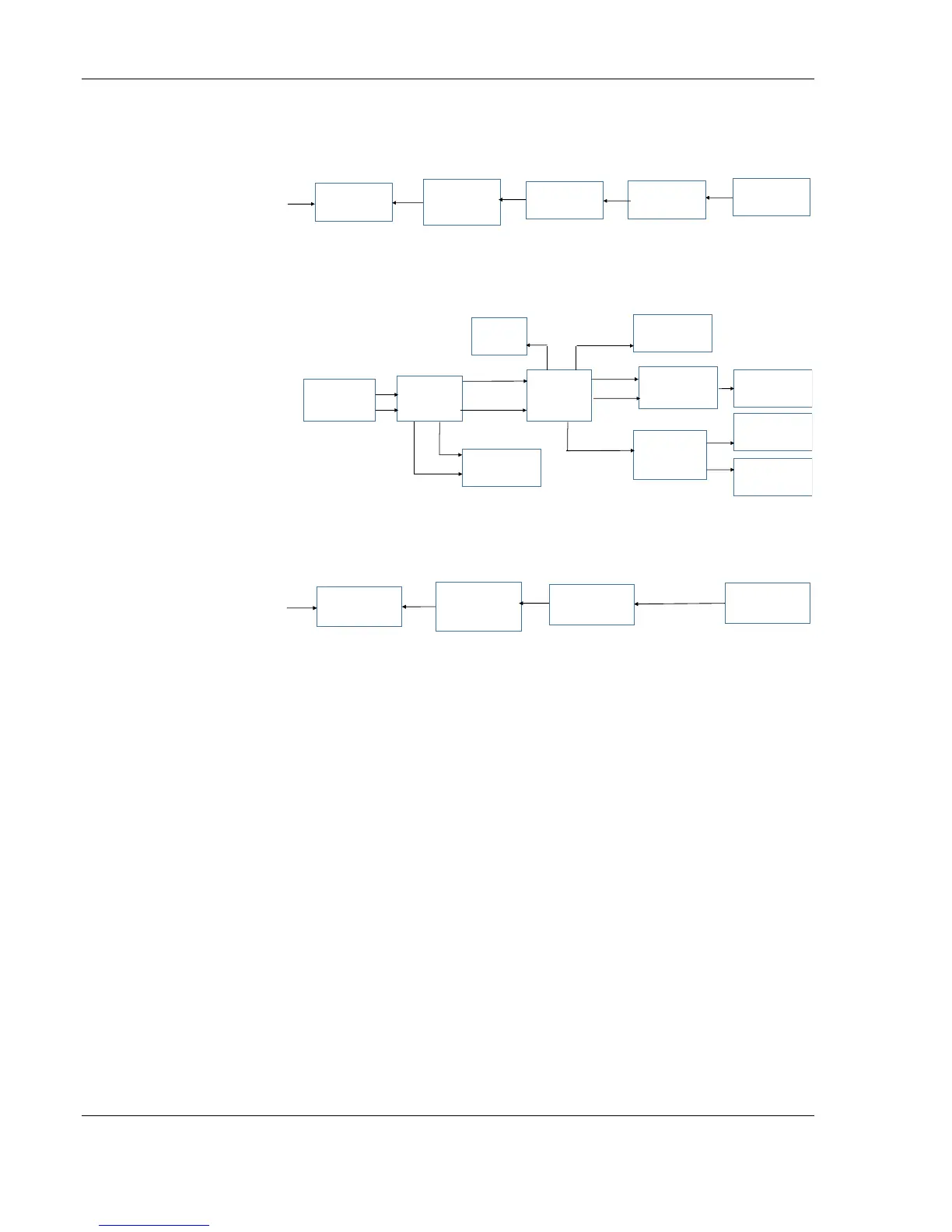
Follows this sequence when the PS_ON signal is (High) available:
Follows this sequence for a Normal Power-up:
Follows this sequence for Power OFF SLEEP:
Voyager Platform Power Module VPPM (Power Supply)
The EPIQ’s main power supply module or VPPM is located in the rear
lower enclosure of the system. It provides automatic worldwide AC
voltage regulation, isolated AC outputs for peripheral equipment,
medically isolated DC voltages for the system, and a Smart Battery
System (SBS) compliant charging system for use with the optional
lithium-ion batteries.
Some key points to be aware of:
Voltages are distributed to the power regulator board (PRB) via
the backplane.
The system monitor is powered by VDC_SYS voltage (+24 Vdc). It
is not powered by the battery, to reduce battery load.
When activating the control panel articulation solenoids, the
PowerSupply
Module
AC
in
PCModul e
Backplane
Power
Distribution
Board
Audio
Input/Output
PowerSupply
Module
PCModule
Bac kplane
Power
Distribution
Board
ControlPanel
Audio
Input/Output
AC
in
SSD
HDDS
Monitor
Acquistion
Module
Acquisition
ControlBoard
Power
Regulator
PWRREGON
VDC_SYS
VDC_SYS
12V,5V
PWROK
ATX
VDC
SYS
ATX
PWRREGON
VDC_SYS,12V,5V,3.3V
VDC_SYS,12V,5V,3.3V
12V,5V
12V,3.3V
PowerSupply
Module
AC
in
PCModule
Power
Distribution
Board
ControlPanel
All ATX and newer
power supplies use the
PS_ON signal to power
up the system. The
power supply remains in
stand-by mode when
the system is plugged in
and the system is off.
Note: This mode of power
up is for moving the
system.