FC7070/01 /11 /61 /81
2-9
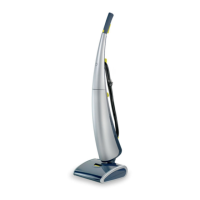
Capacitive
Power
Supply
Main
PCBA
Inter-
connect
PCBA
Clutch PCBA
CWT PCBA
DWT PCBA
Hood Switch
Dead Man Switch
Life
Neutral
Upper Stick Lower Stick Nozzle
Relay
SPST
Relay
SPST
(pulsed)
MCU
MCU
Fan
Pump Brush
LED
H2
H1
Hall
Sensor
Capaci-
tive
Sensor
Resistive
Power
Supply
Isolated
Power
Supply
Back-
up
Power
M
M M
230 VAC
DISASSEMBLY- AND RE-ASSEMBLY ADVISE
The system consists of three major parts:
- Upper Stick
- Lower Stick
- Nozzle
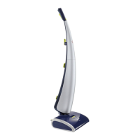
Upper / Lower stick
Remove the decorative front covers of both the Upper
Stick and Lower stick.
To prevent scratches or damage it is advisable to detach
the decorative covers and store them aside. To remove the
decorative cover of the upper stick, take a small at-head
screwdriver and unlock the six snaps as indicated in the
illustration below. Carefully move the panel forward, there are
eight pillars guiding the panel on the frame behind.
To remove the decorative cover of the lower stick, take a
small at-head screwdriver and unlock the eight snaps as
indicated in the illustration below. Carefully move the panel
forward, there are eight pillars guiding the panel on the frame
behind.
Electrical diagram: