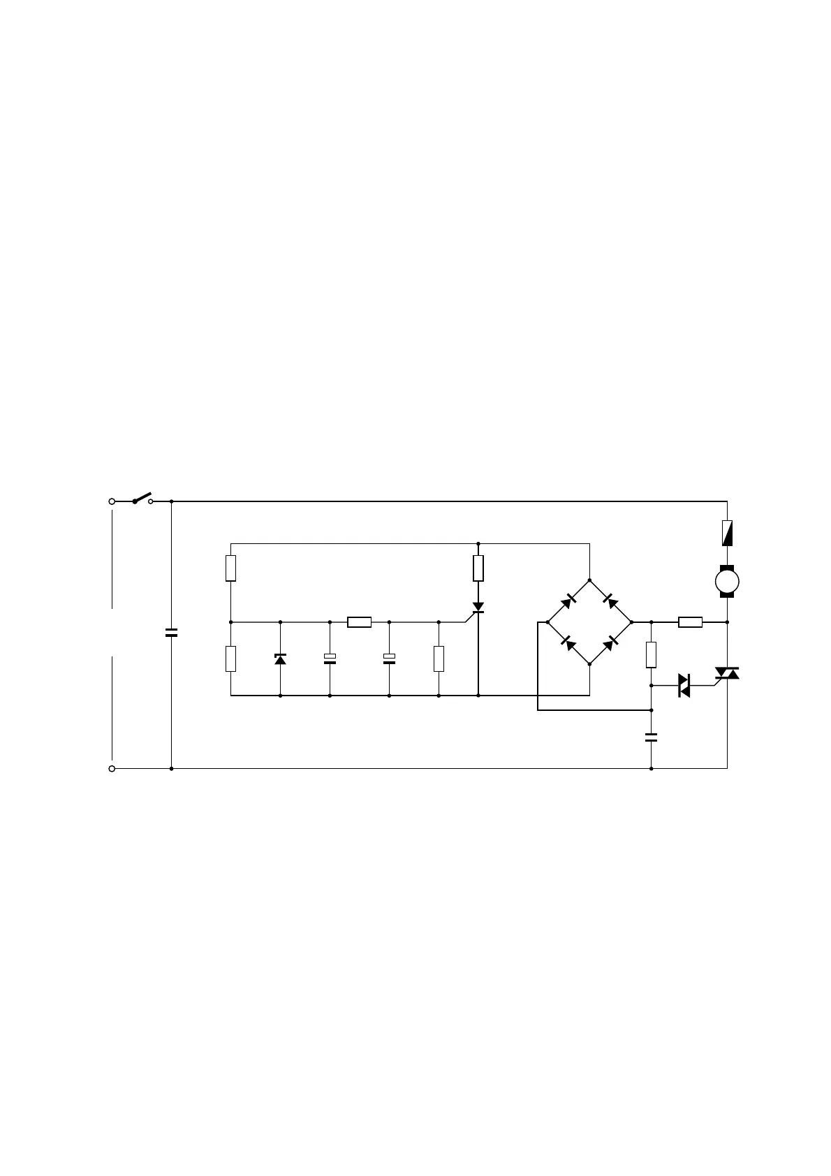
FC8473/01 / FC8473/61
3-10
M
D2
D3
D4
D1
K
AC
220 - 240V
50Hz
C1
0.47µF
275V
C2
0.22µF
400V
L
N
Motor
TMP
TR1
R1
2k-¼W
R6
18k-¼W
D5
DB3
4x
1N4007
R2
180k
T2
MCR100-6
R7
27k
¼W
R3
3.9k
¼W
R4
300k
¼W
R5
47k
¼W
C4
220µF
16V
C4
220µF
16V
DW1
10V
½W
CIRCUIT DIAGRAM
DISASSEMBLY- AND RE-ASSEMBLY ADVISE
• The Motor housing is fixed around the motor with two
screws (E) and clicknocks all around and, these can easily
be detached and clicked in again while assembling.
• Working procedure for re-assembling the Upper housing:
First click the snap locks on the backside of the Upper
housing then assemble the frontside and tighten the 6
screws (B).