FC9910/01/B
System confi guration:
Bumper
Front IR
Bottom IR
Bottom PSD
Button
Dustbin
Lift
Wheel
Motor
Suction
Motor
Side Brush
Motor
Brush
Motor
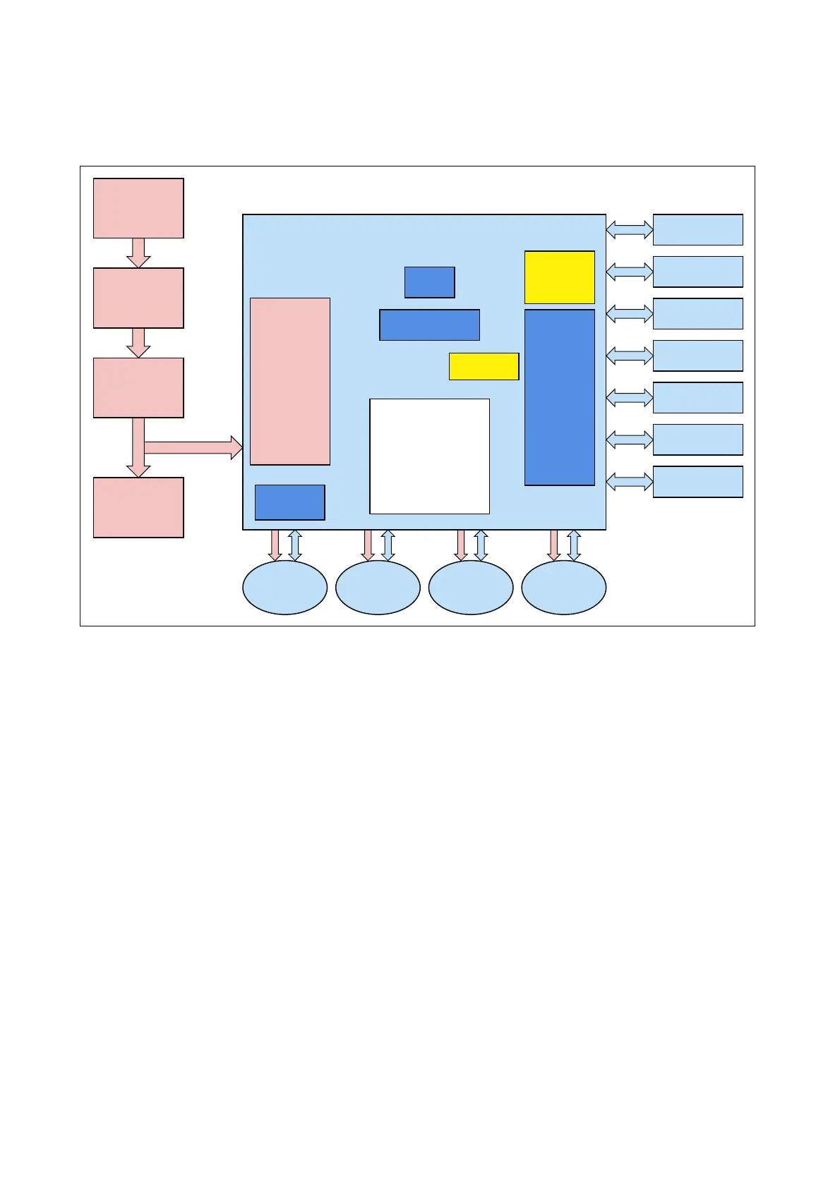
HomeRun Block diagram
Motor
Driver
Control
CPU
RTC
battery
CAM
CPU Board
Buzzer
Display
LED block
SMPS
V
bat
12V
5V
3V3
Adaptor
(19V)
Base
Station
Charger
Board
Battery
(Li-ion)
Main (Control) Board
DESCRIPTION OPERATING PRINCIPLE
- The main board consists of the Power supply, CPU-board,
Real Time Clock, Motor drivers, Display and Camera unit
and thus is controlling the whole system with regard to
input/output processing, motor operation and others.
- The charging board charges the battery with the electrical
source supplied from the 19 V mains adapter and also gives
input to the control board regarding battery condition.
- The User interface board contains the interface buttons.
It also contains the Remote control reception device.
- 6 motors are used in the Robot body:
2 wheel motors, 1 main brush motor, 2 side brush motors
and 1 vacuum motor.
Sensors
- The Bumper sensor exists of an outer carbon rubber that
makes contact with an inner patterned film when colliding.
It is divided in 6 different contact areas, four at the front
and two at the front upper side.
- The Front IR sensors are placed to detect obstructions
without contacting, in addition to above bumper sensor.
A total of 7 IR sensors are mounted for this function.
- The Ground Detection IR sensors are placed in the bottom
to detect there is a “precipice”
- Wheel Lift Detection sensors are located on both wheels to
detect if a wheel is raised.
-A Dustbin Detection sensor is mounted to detect dustbin
is in place.
-A Camera unit at the top cover is used for mapping the
room by means of the sealing/wall structure.
-A Passive Encoder is attached to the front wheel to measure
the travel distance.
-A Gyro sensor is mounted to measure the rotation angle.
4-17