EasyManua.ls Logo

Philips FW-C280/22 User Manual

Philips FW-C280/22
40 pages
To Next Page IconTo Next Page
Page #1 background imageLoading...
Page #1 background image
CLASS 1
LASER PRODUCT
COMPACT
DIGITAL AUDIO
Service Manual
Service
Service
Service
FW-C280/22/34
TABLE OF CONTENTS
Page
Location of pc boards & Version variations ................1-2
Technical Specifications .............................................1-3
Measurement setup ....................................................1-4
Service Aids, Safety Instruction, etc...........................1-5
Instruction for use: European version excerpt..........2-1
Disassembly Instructions & Service positions ...........3-1
Service Test Programs ...............................................3-4
Set Block diagram ......................................................... 4
Set Wiring diagram ........................................................ 5
Front Board .................................................................... 6
Tuner Board: ECO5 Sys .......................................... 7B
Tuner 95............................................. 7D
ETF7 Tape Module ........................................................ 9
3CDC-LC-MB Module............................................... 10A
Combi Board ................................................................ 11
Set Mechanical Exploded view & parts list ................. 12
©
Copyright 2000 Philips Consumer Electronics B.V. Eindhoven, The Netherlands
All rights reserved. No part of this publication may be reproduced, stored in a retrieval system or
transmitted, in any form or by any means, electronic, mechanical, photocopying, or otherwise
without the prior permission of Philips.
Published by KC 0050 Service Audio Printed in The Netherlands Subject to modification
GB
3139 785 22610
Mini System
Question and Answer IconNeed help?

Do you have a question about the Philips FW-C280/22 and is the answer not in the manual?

Philips FW-C280/22 Specifications

General IconGeneral
Tuner BandsFM
ConnectivityUSB, Aux-in
Number of Discs1
CD PlayerYes
USB PlaybackYes
FM RadioYes
BluetoothNo
TypeStereo System
Disc PlaybackCD, CD-R/RW
Speaker Type2-way

Summary

Location of PC Boards

Version Variations

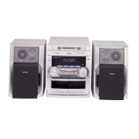
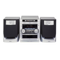
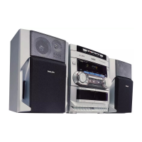
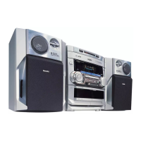
Details on different hardware configurations and features for various models.

Specifications

General Specifications

Covers mains voltage, frequency, power consumption, clock accuracy, and dimensions.

Amplifier Specifications

Details output power, frequency response, dynamic bass boost, and sound features.

Tuner Specifications

Provides FM, MW, and LW tuning range, sensitivity, selectivity, and rejection.

Measurement Setup

FM Tuner Measurement Setup

Describes the test configuration and equipment for FM tuner measurements.

AM (MW, LW) Tuner Measurement Setup

Details the setup for AM tuner measurements, including Faraday cage use.

ESD Safety and General Warnings

ESD Precautions

Highlights risks of electrostatic discharge to ICs and semiconductors during repair.

General Safety Instructions

Emphasizes restoring the unit to original condition and using identical parts.

Service Test Program

Tuner Test Procedures

Details on performing tests on the tuner section and its frequencies.

Set Block Diagram

Set Wiring Diagram

Front Board

Component Layout

Visual representation of component placement on the front board.

Electrical Parts List

Comprehensive list of electrical components used on the front board.

Tuner Board ECO5

Tuner 95 Board

Adjustment Table

Alignment procedures and frequency settings for the TUNER 95 board.

Circuit Diagram

Schematic of the TUNER 95 board's electronic circuits.

ETF7 Tape Module

Analog Circuit Diagram

Schematic diagram of the tape module's analog signal processing circuits.

Servo Circuit Diagram

Schematic of the tape module's servo control circuits for motor operation.

Related product manuals