B
A
B
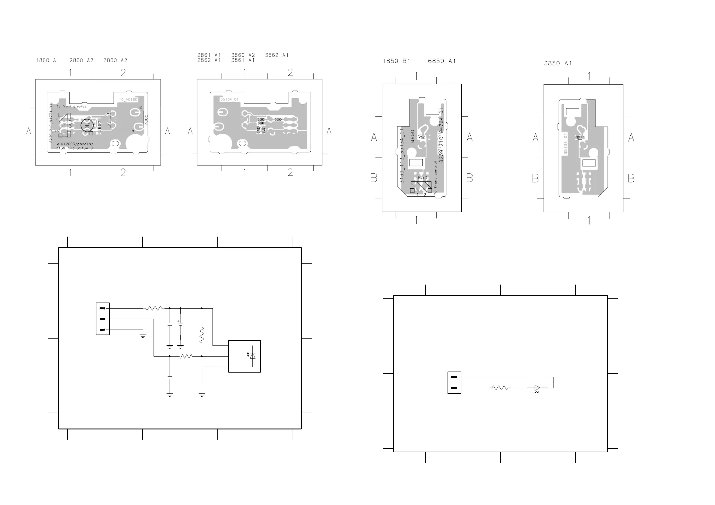
1860 A1 2860 A2 2861 B2 2862 A2 3860 A2
123
123
A
EH-B
1860
1
2
3
3861 B2 3862 A2 7800 A3
Gnd
47u
2860
GND
2
GND
OUT
VS
Gnd
TSOP4836ZC1
7800
Gnd
Gnd Gnd
47n
2862
2861
2n2
100R
3860
3861
1K
3862
10K
3139 118 56720...8239_210_94774 for 3513 pt4 dd wk0310
Note : Some values may varies, see respective
parts list for correct value.
IR EYE
This assembly drawing shows a summary of all possible versions. For components
used in a specific version see schematic diagram and respective parts list.
3139 113 3513 pt4 dd wk0310
This assembly drawing shows a summary of all possible versions. For components
used in a specific version see schematic diagram and respective parts list.
3139 113 3513 pt4 dd wk0310
A
B
1850 A1 3850 B1 6850 B2
12
12
A
B
EH-B
1850
1
2
LTL-8166FTNN
6850
3850
820R
3139 118 56720...8239_210_94784 for 3513 pt4 dd wk0310
Note : Some values may varies, see respective
parts list for correct value.
USB LED
This assembly drawing shows a summary of all
possible versions. For components used in a
specific version see schematic diagram and
respective
parts list.
3139 113 3513 pt4 dd wk0310
This assembly drawing shows a summary of all
possible versions. For components used in a
specific version see schematic diagram and
respective
parts list.
3139 113 3513 pt4 dd wk0310
USB LED BOARD - COMPONENT LAYOUT USB LED BOARD - CHIP LAYOUT
USB LED BOARD - CIRCUIT DIAGRAM
IR EYE BOARD - COMPONENT LAYOUT IR EYE BOARD - CHIP LAYOUT
IR EYE BOARD - CIRCUIT DIAGRAM
5-8 5-8