EasyManua.ls Logo

Philips FW-C579 User Manual

Philips FW-C579
72 pages
To Next Page IconTo Next Page
Page #1 background imageLoading...
Page #1 background image
GB
CLASS 1
LASER PRODUCT
COMPACT
DIGITAL AUDIO
Service Manual
Service
Service
Service
Service
Service
FW-C579/37
TABLE OF CONTENTS
Page
Location of pc boards & Version variations ................1-2
Technical Specifications .............................................1-3
Measurement setup ....................................................1-4
Service Aids, Safety Instruction, etc...........................1-5
Disassembly Instructions & Service positions .............. 2
Service Test Programs .................................................. 3
Set Block diagram ......................................................4-1
Set Wiring diagram .....................................................4-2
Front Control Board ....................................................... 5
Front Display Board ....................................................... 6
ECO6 Tuner Board : Systems Non-Cenelec............. 7A
AF11 Board .................................................................... 8
P2002 110/135W Module .............................................. 9
5DTC Module (Basic Version) ..................................... 10
Set Mechanical Exploded view & parts list ................. 11
Revision List ................................................................ 12
©
Copyright 2003 Philips Consumer Electronics B.V. Eindhoven, The Netherlands
All rights reserved. No part of this publication may be reproduced, stored in a retrieval system or
transmitted, in any form or by any means, electronic, mechanical, photocopying, or otherwise
without the prior permission of Philips.
Published by BB 0312 Service Audio Printed in The Netherlands Subject to modification
Mini System
3139 785 30311
Version 1.1
For repair information on the Subwoofer, please refer to Service Manual
of Active Subwoofer SW579/17 (12NC : 3139 785 30390).
Question and Answer IconNeed help?

Do you have a question about the Philips FW-C579 and is the answer not in the manual?

Philips FW-C579 Specifications

General IconGeneral
TypeMini Hi-Fi System
CD PlayerYes
Number of Discs1
Playable MediaCD, CD-R, CD-RW, MP3-CD
Audio FormatsMP3
Radio Presets20
BluetoothNo
USB PlaybackNo
EqualizerYes
Headphone JackYes
Remote ControlYes
Weight3.5 kg
Radio TunerFM
Speakers2
ConnectivityAUX

Summary

Service Manual

Specifications

Detailed technical specifications for the system's various functions and components.

Measurement Setup

Procedures and diagrams for measuring system performance parameters.

Safety and Warning Information

Crucial safety warnings regarding ESD, laser radiation, and general repair precautions.

Dismantling Instructions

Dismantling the 5DTC Module

Procedure for removing the cover, panels, and the 5DTC module itself.

Dismantling Front Control and Display Boards

Procedure for removing knobs, boards, and brackets from the front assembly.

Dismantling of the Rear Panel Assembly

Steps to remove tuner board, AF board, video out board, mains socket board, and fan.

Detaching the Front Panel Assembly

Steps to separate the front panel from the main chassis assembly.

Service Test Program

Set Block Diagram

Set Wiring Diagram

Control Board Circuit Diagram

Display Board Circuit Diagram

ECO6 Tuner Board

Tuner Board ECO6 Systems Non Cenelec

Tuner Adjustment Table

Table detailing tuning adjustments for FM, MW, and LW bands, including VCO and AM AFC.

AF11 Board Circuit Diagram (Part 1)

AF11 Board Circuit Diagram (Part 2)

AF11 Board Circuit Diagram (Part 3)

P2002 110/135W Module

Mains Board Circuit Diagram

Left/Right Amplifier & Supply Board Component View

L/R Amplifier & Supply Board Circuit Diagram (Part 1)

L/R Amplifier & Supply Board Circuit Diagram (Part 2)

L/R Amplifier & Supply Board Circuit Diagram (Part 3)

5DTC Module (Basic Version)

Service Hints

Troubleshooting steps for CD playback issues, including verification and lens cleaning.

Wiring Diagram 5DTC Module

Diagram illustrating FFC cable connections between boards in the 5DTC module.
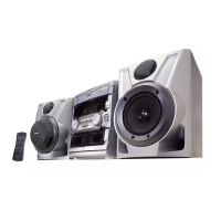
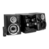
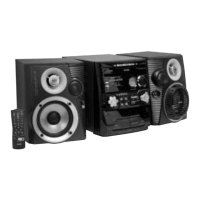
Service Hints

CD Drive Replacement Warning

Wiring Diagram 5DTC Module

Block Diagram 5DTC CD Version

Exploded View 5DTC Mechanic

Related product manuals