DISMANTLING INSTRUCTIONS
Dismantling of the 5DTC Module
1) Loosen 4 screws to remove the Cover Top (pos 255) by
sliding it out towards the rear before lifting up.
- 2 screws on the rear
- 1 screw each on the left & right side
2) Loosen 3 screws each to remove the Panel Left (pos 253)
and Panel Right (pos 254). The Panels are removed by
sliding it towards the rear and outwards.
- 2 screws on the rear
- 1 screw on the side
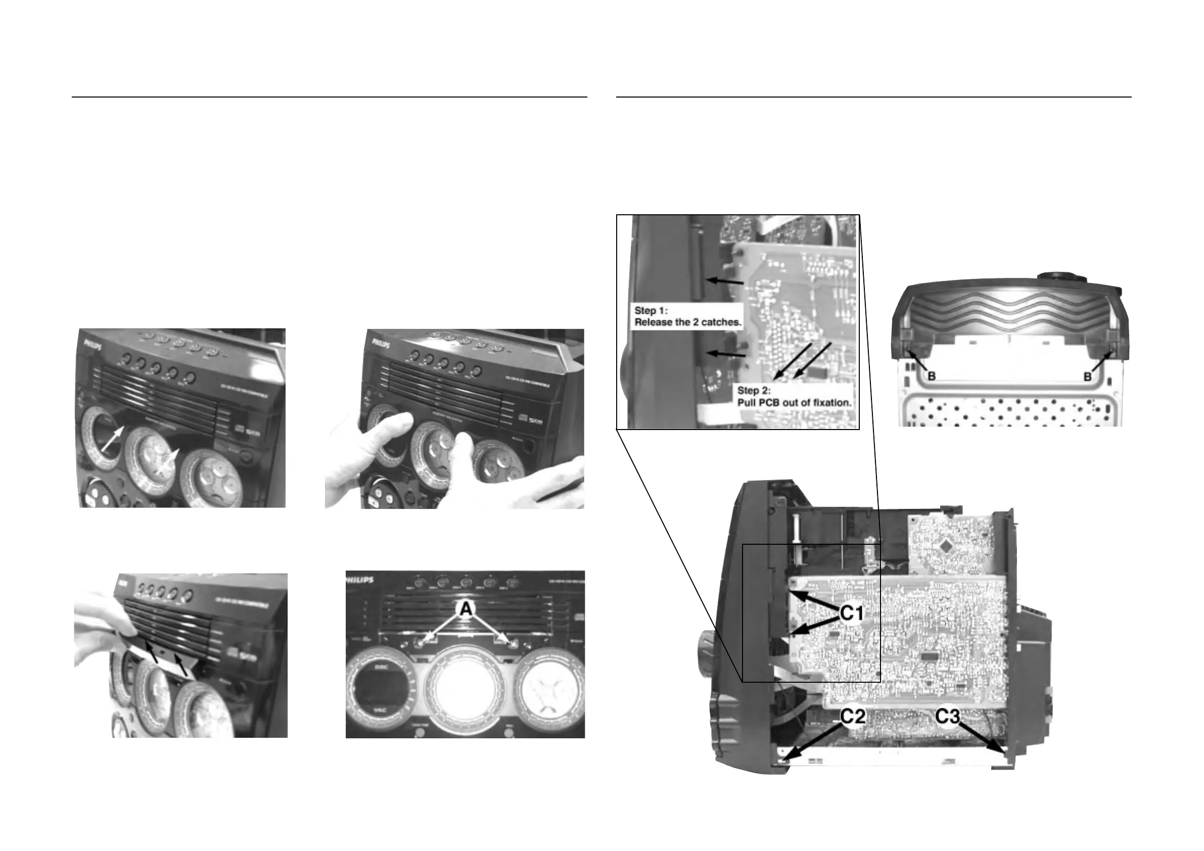
1) Remove 2 screws B (pos 226) as shown in Figure 5 from
the bottom of the Cabinet Front (pos 101).
Detaching the Front Panel assembly from the Bottom/Rear assembly
2-1 2-1
Figure 1
Figure 3
Figure 2
Figure 4
3) To loosen the Panel Front Display (pos 120), you have to
press in the correct direction and position as shown in
Figure 1 and Figure 2. Once the Panel Front Display is
loosen, remove it out in the direction as shown in Figure 3.
4) Loosen 4 screws A (see Figure 4 and Figure 16) to remove
the 5DTC Module (pos 1105).
- 2 screws on the front
- 2 screws on the rear
Note : For information on the 'Emergency opening of the
trays' of the 5DTC Module, refer to Chapter 10
(Page 10-7).
Figure 5
2) Release the fixation of the AF Board (pos1102-A) to
Bracket CDC Right (pos 186) by releasing the 2 catches
C1 (see Figure 7) and pulling the AF Board outwards as
shown in Figure 6.
3) Uncatch 2 catches C2 (see Figure 7) on the left & right
sides of the Cabinet Front (pos 101) and slides the Front
Panel assembly out towards the front.
Figure 6
Figure 7