ADJUSTMENT AND CONTROLS
Thermostat :
Thermostat 20, fitted to the solplate 25 has already been adjusted by the supplier and secured by glue.
To avoid mal-function of the iron, NEVER re-adjust the thermostat.
Adjustment thermostat 20, supplied as a spare part.
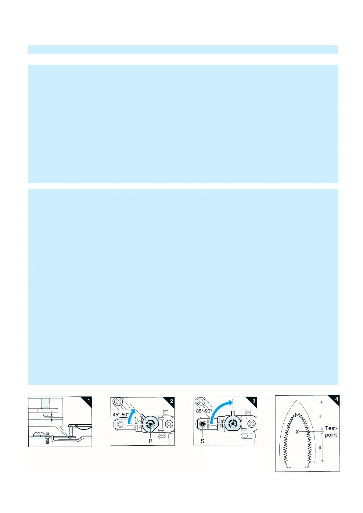
N.B. Before starting to adjust the thermostat, make sure that a gap exists between the lower tip of the ceramic
insulating pin and the real-off bracket. See fig. 1.
Connect the connecting strips to an Ohm-meter.
Set the thermostat stopper to the position as indicated in fig. 2.
Turn the adjusting screw (R) clockwise or anti-clockwise until the Ohm-meter indicates"0".
(The contacts closed)
Then turn the adjusting screw clockwise until the Ohm-meter indicates ∞ and the contacts have only just been opened.
You hear a "click".
While loosely turning the thermostat stopper, check if the thermostat switches in the position as indicated in fig. 2.
After the thermostat has been adjusted, adjust the real-off bracket.
Set the thermostat stopper in the position shown in fig. 3.
The thermostat contacts are closed. (Ohm-meter indicates "0")
Turn the set-screw S clockwise until the contacts have only just been opened.
The Ohm-meter indicates ∞.
Secure the adjusting screws with a glue.
After adjusting the thermostat, always check the temperature of the soleplate, with the dial set to MAX. position (215° ±25°C)
For location of testing point, see fig. 4.
The temperature must be measured, after the iron has been connected to the mains for at least 15 min.
The max. temperature shall not be higher than 240°C.
IMPORTANT + ADJUSTMENT AND CONTROLS
IMPORTANT
Due to the high wattage of the iron, only the specified cordsets must be used.
NOTES :
1) For standardisation reasons :
Dial : With English / Spanish text only.
Rattle spring : 5 pieces will be supplied when ordered
Type plate : No info about the type number and voltage have been stamped onto the typeplate.
When replacing the type plate, engrave at least type number and voltage onto the type
plate with a sharp object.
Slide unit 13 : with blue color only.
2) Parts, with numbers from 100 and higher, cannot be ordered separately.
3) After the product has been repaired, it should function properly and has to meet the safety requirements and legal
regulations as laid down and of
ficially
established at this moment.