3 - 2 3 - 2
SERVICE POSITIONS
Service position A
Note:In some service positions the components or copper patterns of one board may risk touching its neighbouring pc boards or
metallic parts. To prevent such short-circuit use a piece of hard paper or other insulating material between them.
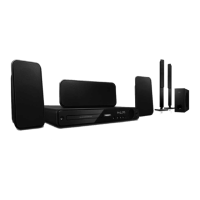
Dismantling of the MAIN+SCART Board
1) Loosen 4 screws “G” on the top of Main Board as shown in gure 11.
2) At the back panel, loosen 9 screws to remove MAIN Board and loosen 2 screw to remove Scart Board as shown in gure 12.
Figure 9
Dismantling of the DISP+LED+VOL&MP3 IN Board
1) Loosen 10 screws “E” on the top of DISP+LED+VOL&MP3 IN Board as shown in gure 8.
Figure 8
Dismantling of the Power Board
1) Loosen 4 screws “F” on the top of Power Board as shown in gure 9.
2) With a pincers to nip this space as shown in gurer 10 and to take up the power board.