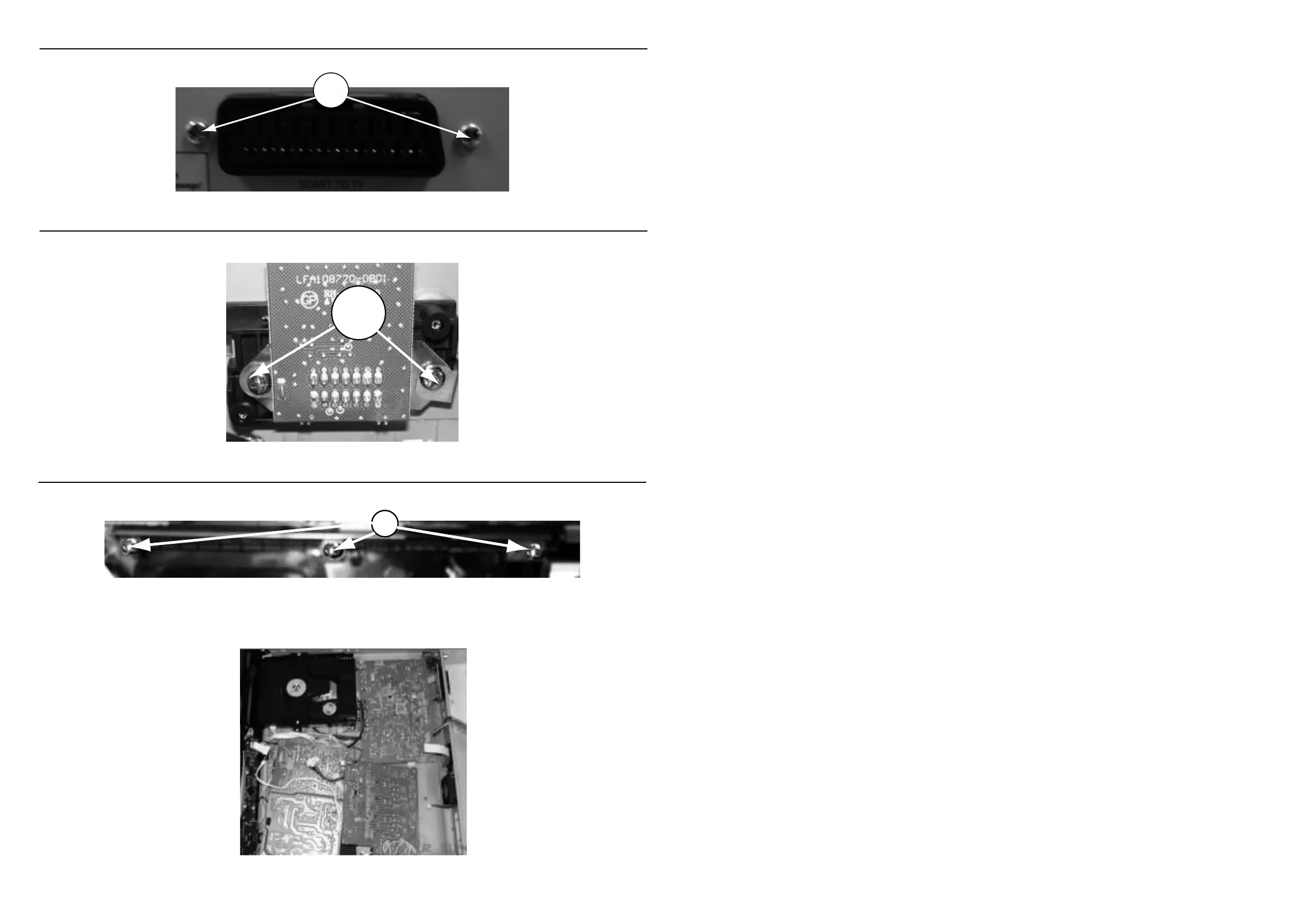
Dismantling of the SCART Board
1) Loosen 2 screws “O” at the back panel as shown in gure 17.
Figure 17
Dismantling of the JACK Board
1) Loosen 2 screws “P” on the top of JACK board as shown in gure 18.
Figure 18
Dismantling of the TOUCH Board
1) Loosen 3 screws “Q” on the top of TOUCH board as shown in gure 19.
Figure 19
SERVICE POSITIONS
Note:In some service positions the components or copper patterns of one board may risk touching its neighbouring pc boards or
metallic parts. To prevent such short-circuit use a piece of hard paper or other insulating material between them.