Mechanical Instructions
EN 11LC7.5E LA 4.
4.3.2 AmbiLight Lamps (if present)
1. Refer to next figure.
2. Unplug connectors [1].
3. Remove the T10 parker screws [2].
4. Remove the unit by shifting it sidewards [3].
When defective, replace the whole unit.
Figure 4-8 AmbiLight lamps
4.3.3 Keyboard Control Panel
1. Refer to next figure.
2. Unplug connector [2].
3. Remove the T10 parker screws [1].
4. Remove the unit.
5. Release clips [3] and remove the board.
When defective, replace the whole unit.
Figure 4-9 Keyboard control panel
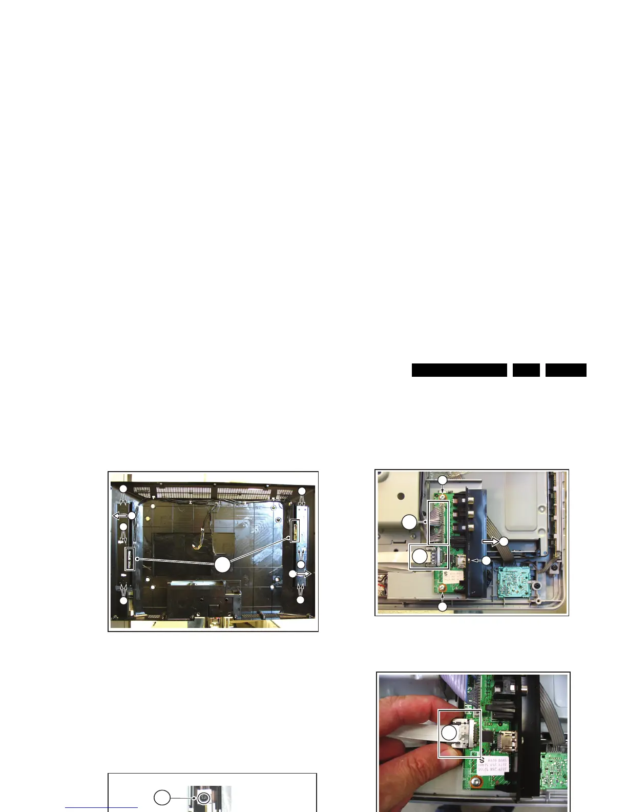
4.3.4 Side I/O Panel
1. Refer to next figures.
2. Unplug connectors [1]. To release the flatcable connector
[1b], push the two side levers and unplug the connector.
3. Remove screws [2] and remove the complete module [3].
When defective, replace the whole unit.
Figure 4-10 Side I/O module (1/2)
Figure 4-11 Side I/O module (2/2)
4.3.5 IR/LED Panel
1. Refer to next figure.
2. Unplug connectors [1].
3. Release clip [2] and remove the board.
When defective, replace the whole unit.
Figure 4-12 IR/LED panel
H_17370_039.eps
080807
1
2
2
2
2
2
2
3
3
G_16850_007.eps
310707
2
1
1
3
H_17370_049.eps
080807
1b
1a
2
2
2
3
H_17370_045.eps
080807
1b
G_16850_009.eps
110107
1
2